Evacuation notification terminal device and evacuation notification system

Inactive Publication Date: 2015-10-15
AKUTSU ICHIRO
View PDF5 Cites 10 Cited by
  • Summary
  • Abstract
  • Description
  • Claims
  • Application Information

AI Technical Summary

Benefits of technology

The present invention is a evacuation notification system that allows for accurate and swift ascertination of evacuation locations and the number of individuals having evacuated during a disaster or alarm. The system includes an evacuation notification terminal device and a receiving terminal device. The evacuation notification terminal device is operated by an evacuee and has a simple arrangement including input means, position-determining means, and transmission means. The device is automatically positioned and sends evacuation notification information including the number of evacuees and position information at a predetermined time interval. The receiving terminal device displays an evacuation position marker on a map and displays the number of evacuees associated with the marker. The system allows a disaster center to accurately ascertain evacuation conditions and quickly organize rescue / support efforts. The evacuation notification terminal device can be provided in an evacuation shelf or lifeboat, allowing for easy and accurate visual ascertination of evacuation conditions and enabling rescue efforts to be rapidly organized.

Problems solved by technology

However, breakwaters were broken by the unexpected massive tsunami produced by the 2011 Tohoku earthquake, failing to stop the onslaught of the tsunami and leading to numerous deaths.
However, even when there are designated tsunami evacuation sites, these are often at higher ground in geographical terms, and it may take effort to reach these evacuation sites, which are not necessarily each to utilize.
Wheelchair users, the elderly, children, and other socially disadvantaged individuals experience particular difficulties.

Method used


Image

  • Evacuation notification terminal device and evacuation notification system
  • Evacuation notification terminal device and evacuation notification system
  • Evacuation notification terminal device and evacuation notification system

Examples


Embodiment Construction

[0034]An embodiment of the evacuation notification system according to the present invention will now be described via specific examples with reference to FIGS. 1-9.

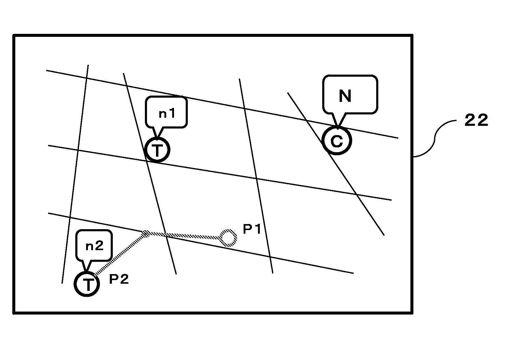
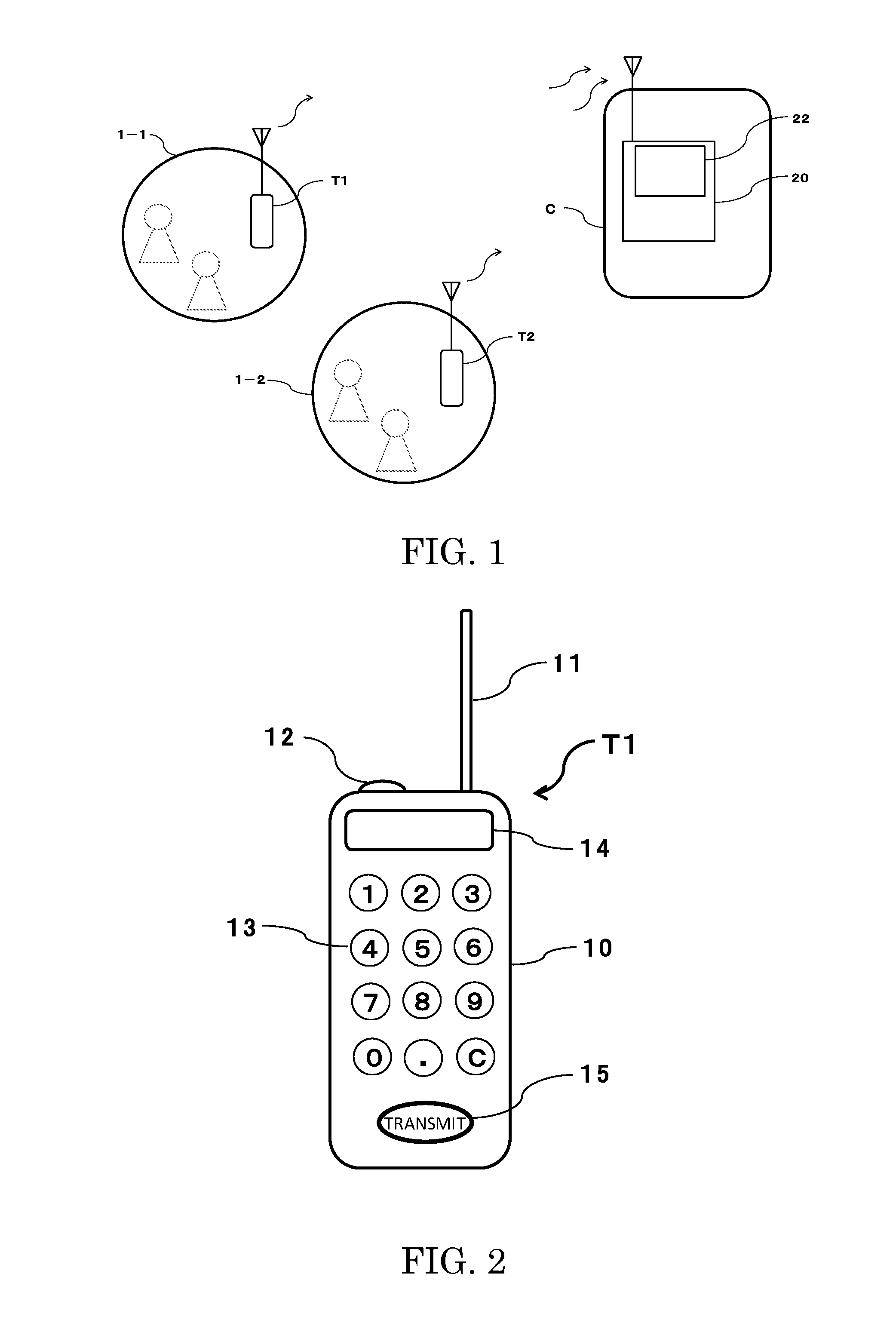
[0035]FIG. 1 shows an overall schematic view of an example of the evacuation notification system according to the present invention. As shown in FIG. 1, an evacuation notification system comprises evacuation notification terminal devices T1, T2 provided at evacuation sites 1-1, 1-2 such as an emergency evacuation apparatus, an emergency evacuation apparatus such as an emergency evacuation shelter, a designated evacuation facility (school, civic hall, etc.), or a designated evacuation location, and a receiving terminal device 20 provided at a disaster center C serving as an evacuation monitoring location. FIG. 1 shows typical examples of evacuation sites; in actuality, more evacuation sites will be present. An evacuation notification terminal device T is provided at each evacuation site. The receiving terminal device 20 i...


PUM


Abstract

The present invention provides an evacuation notification system that can provide notification of the number of evacuees taking shelter in multiple emergency evacuation facilities or apparatus, and allows evacuation conditions to be accurately ascertained on the basis of such notifications.An evacuation notification system comprises an evacuation notification terminal device that is capable of automatically transmitting evacuation notification information including an inputted number of evacuees, a determined evacuation position, and identifying information at a predetermined time interval and is provided at an evacuation site, and a receiving terminal device in a disaster center that displays an evacuation position marker on a map displayed on a terminal screen and a number of evacuees associated with the marker on the basis of the number of evacuees, evacuation position, and identifying information included in the received evacuation notification information transmitted from the evacuation notification terminal device, and can display movement history.

Description

TECHNICAL FIELD[0001]The present invention relates to an evacuation notification terminal device and an evacuation notification system that notifies an evacuation monitoring location (such as a disaster center set up by local authorities) of the number of evacuees at an evacuation site when a natural disaster such as a tsunami or flood occurs or when an evacuation warning is issued, allowing evacuation status to be swiftly and precisely ascertained.TECHNICAL BACKGROUND[0002]Generally, strategies for combating water-related disasters such as tsunamis and floods have centered on local authorities. In the case of tsunamis, for example, massive breakwaters are built to prepare for the onset of tsunamis, or the authorities may instruct the populace to quickly evacuate to higher ground when a tsunami warning is issued.[0003]However, breakwaters were broken by the unexpected massive tsunami produced by the 2011 Tohoku earthquake, failing to stop the onslaught of the tsunami and leading to ...

Claims


Application Information

Patent Timeline
IPC IPC(8): H04W4/22H04W4/02H04W4/90H04W4/029
CPCH04W4/02H04W4/22H04W4/90H04W4/029
Inventor AKUTSU, ICHIRO
Owner AKUTSU ICHIRO
Why Eureka
Try Eureka