
System and method for trailing edge noise reduction of a wind turbine blade

a wind turbine blade and trailing edge technology, which is applied in the direction of machines/engines, mechanical equipment, liquid fuel engines, etc., can solve the problems of large operational levels, large levels of trailing edge noise, and tonal noise formation at the trailing edge, so as to reduce the strength of vortex shedding

Active Publication Date: 2015-10-15
LM WP PATENT HLDG
View PDF5 Cites 18 Cited by
  • Summary
  • Abstract
  • Description
  • Claims
  • Application Information

AI Technical Summary

Benefits of technology

The patent describes a method to reduce the noise generated by a wind turbine blade's trailing edge. The method involves increasing the size of the blade's trailing edge, which reduces the strength of the vortex shedding that forms behind the blade. This change in the blade's shape prevents the formation of sustainable vortex shedding patterns that produce noise. Ultimately, this method reduces the size of the vortex shedding, resulting in quieter operation of the wind turbine.

Problems solved by technology

Accordingly, this can lead to relatively large levels of trailing edge noise.
However, one of the disadvantages of such a thick or blunt trailing edge profile is the relatively large levels of operational noise created by the trailing edge, primarily due to vortex shedding behind the trailing edge caused by the meeting of the suction side and pressure side flows, which can result in tonal noise formation at the trailing edge.
However, the splitter plate can be easily damaged during blade operation, requiring on-site replacement.
Furthermore, the projecting arrangement of the splitter plate can introduce complexities into the handling and maintenance operations required for a wind turbine blade.

Method used


Image

  • System and method for trailing edge noise reduction of a wind turbine blade
  • System and method for trailing edge noise reduction of a wind turbine blade
  • System and method for trailing edge noise reduction of a wind turbine blade

Examples


first embodiment

[0082]FIG. 4 illustrates an enlarged cross-sectional view of a blade trailing edge according to the invention;

[0083]FIG. 5 shows enlarged cross-sectional views of wedge elements used in embodiments of the invention;

second embodiment

[0084]FIG. 6 illustrates an enlarged cross-sectional view of a blade trailing edge according to the invention;

[0085]FIG. 7 is an isometric perspective view of the blade trailing edge of FIG. 5;

[0086]FIG. 8 shows a pair of plots of velocity magnitude contours with streamlines for a blade trailing edge having a wedge element according to the invention, and a prior art blade trailing edge without a wedge element according to the invention;

[0087]FIG. 9 illustrates a sample pair of airfoil profiles used in simulation, having both clean and wedge-based blunt trailing edges;

[0088]FIG. 10 presents plots of simulation results for lift coefficients and trailing edge noise levels based on the airfoil profiles of FIG. 9; and

[0089]FIG. 11 illustrates examples of trailing edge solid angles for different blunt trailing edge airfoil profiles.

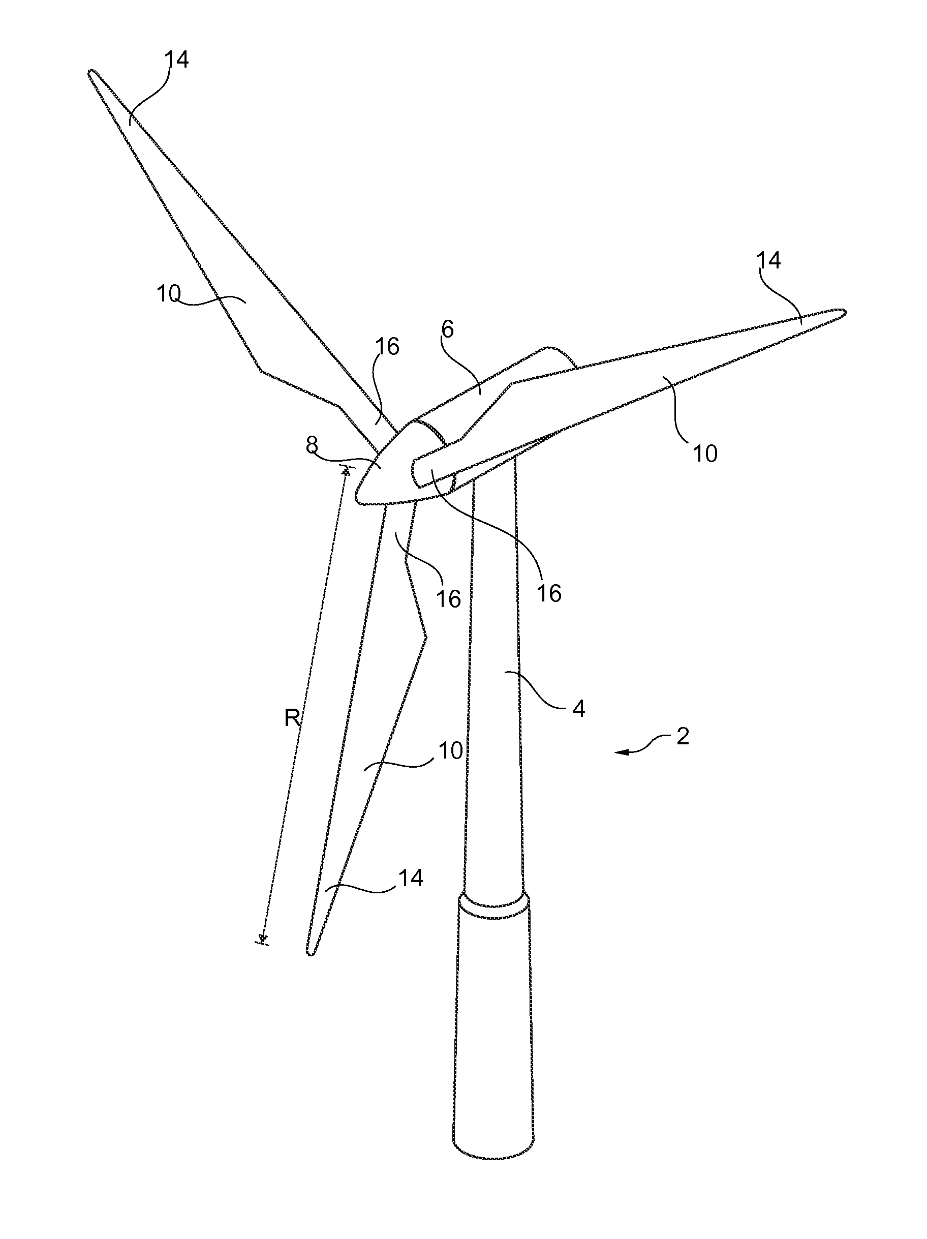
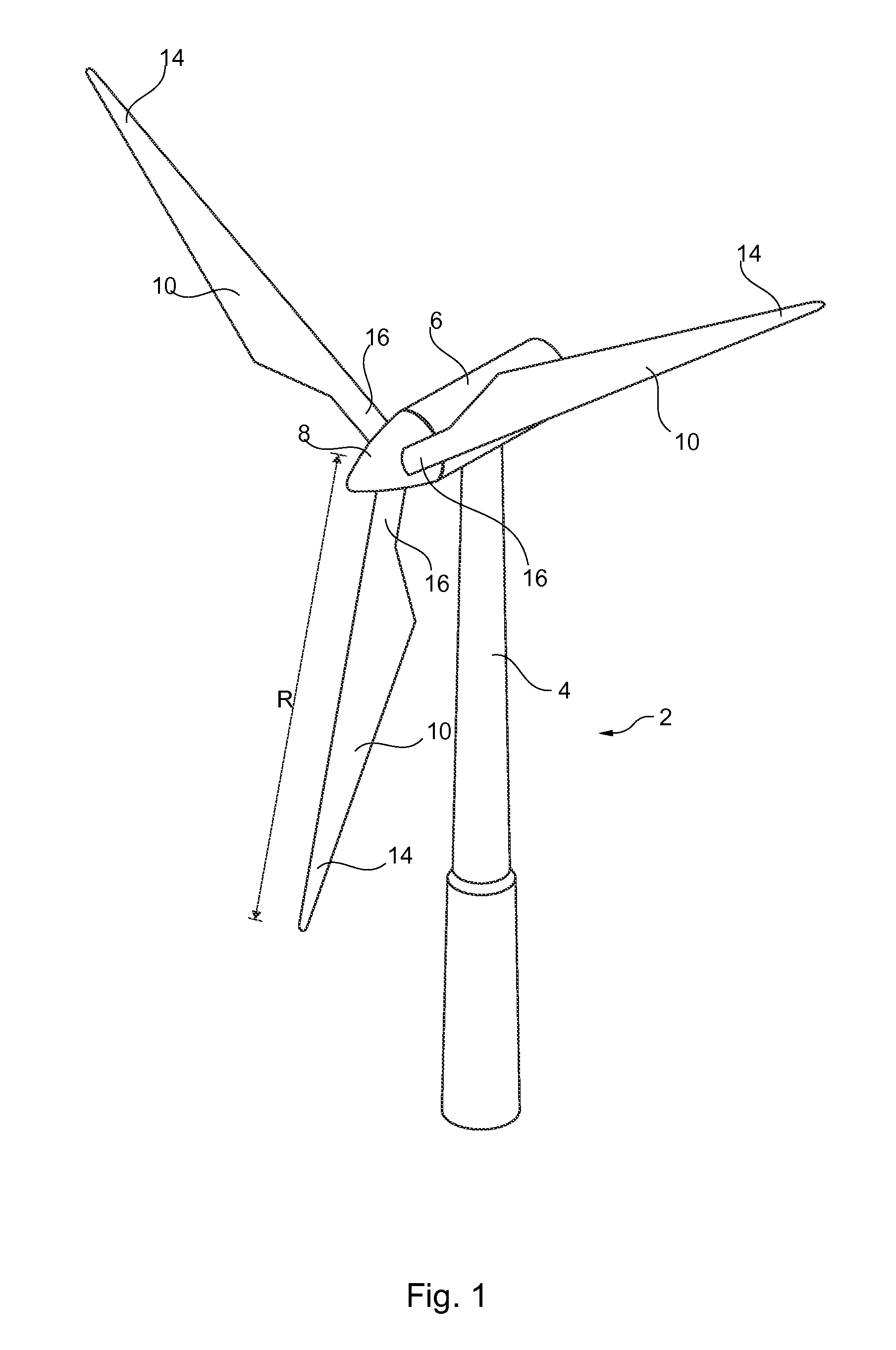
[0090]FIG. 1 illustrates a conventional modern upwind wind turbine according to the so-called “Danish concept” with a tower 4, a nacelle 6 and a rotor with a s...


PUM


Abstract

A system and method for reducing the operational noise of a blunt trailing edge of a wind turbine blade is described. The system involves increasing the trailing edge solid angle at the blade trailing edge by providing a wedge element or projection adjacent the trailing edge of the blade, the wedge element acting to provide improved mixing of the suction side and pressure side flows at the blunt trailing edge, thereby reducing the strength of vortex shedding at the trailing edge and the associated operational noise.

Description

FIELD OF THE INVENTION[0001]The present invention relates to a system and associated method for providing a wind turbine blade having reduced operational noise, in particular a wind turbine blade having reduced trailing edge operational noise.BACKGROUND OF THE INVENTION[0002]One of the continued considerations for wind turbine blade design is the operational noise produced when such blades rotate, in particular for on-shore wind turbine installations. A portion of such noise is generated from airflow leaving the profile of a wind turbine blade at the blade trailing edge, and is often referred to as trailing edge noise.[0003]As modem wind turbine blades are manufactured at increasingly longer blade lengths, the longer span of the blades results in higher relative wind speeds experienced by the blades. Accordingly, this can lead to relatively large levels of trailing edge noise.[0004]Additionally or alternatively, wind turbine blades are sometimes produced having an airfoil profile co...

Claims


Application Information

Patent Timeline
IPC IPC(8): F04D29/66F03D1/06
CPCF04D29/667F03D1/065F03D1/0641F03D7/0296F03D80/00Y02E10/72F03D1/0675
Inventor SINGH, ASHISHRAMANATHAN, GANESHBIJLANI, JITENDRAPARIHAR, NAVEEN
Owner LM WP PATENT HLDG
Learn More