
Support framework for building casing, building casing, building structure and method for manufacturing thereof

a technology for supporting frameworks and building casings, which is applied in the direction of ventilation systems, heating types, lighting and heating apparatus, etc. it can solve the problems of breaking walls, affecting the operation of the building, and not being able to modify the walls

Active Publication Date: 2015-10-01
TOP GLASS EU +2
View PDF11 Cites 9 Cited by
  • Summary
  • Abstract
  • Description
  • Claims
  • Application Information

AI Technical Summary

Benefits of technology

The patent is about a support framework, manufacturing process, installation, and casing and dwelling structure that can achieve certain purposes. The technical effect of this invention is to provide a versatile and effective solution for supporting and stabilizing structures, which can be used in various applications such as manufacturing and installation.

Problems solved by technology

Wet wall structures are substantially monolithic; once the concrete has dried, the wall is not modifiable if not with invasive and destructive interventions.
The compact structure of this type of casing makes plant integration particularly problematic (arrangement of tubes, cables, electric switches, taps).
Breaking walls means defining mechanically weakened zones and creating discontinuities in the heating and acoustic insulation.
A further drawback of this type of wall is constituted by the poor resistance to seismic events (rigid structures): for this reason, in earthquake-prone zones, the walls are reinforced with special stiffeners.
In fact, even wall structures made using dry methods suffer from poor plant-integrating properties (for example electrical and hydraulic plant): in fact eventual modification to plants at times subsequent to their installation are difficult to carry out.
A further limitation of the dry structures at present known is constituted by the high coefficient of heat conductivity of the wall: dry casings do not provide sufficient heat insulation of rooms of the building with respect to the outside.
Dry walls also provide an inadequate acoustic insulation.
Drywall structures further suffer from poor mechanical characteristics (they cannot bear heavy loads): in fact the loads applicable to drywalls are always very small, for example furnishings, shelving or the like.

Method used


Image

  • Support framework for building casing, building casing, building structure and method for manufacturing thereof
  • Support framework for building casing, building casing, building structure and method for manufacturing thereof
  • Support framework for building casing, building casing, building structure and method for manufacturing thereof

Examples


Embodiment Construction

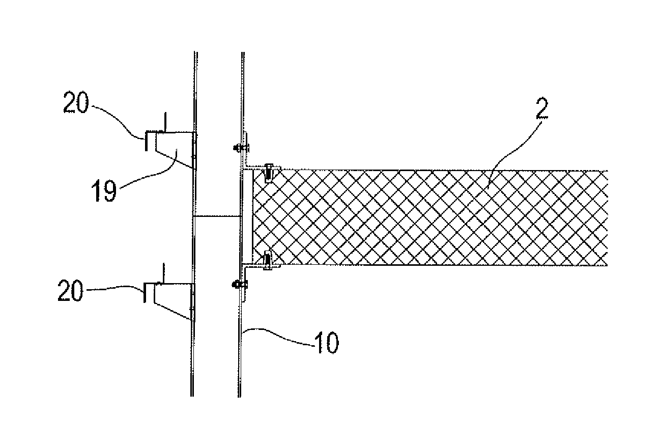
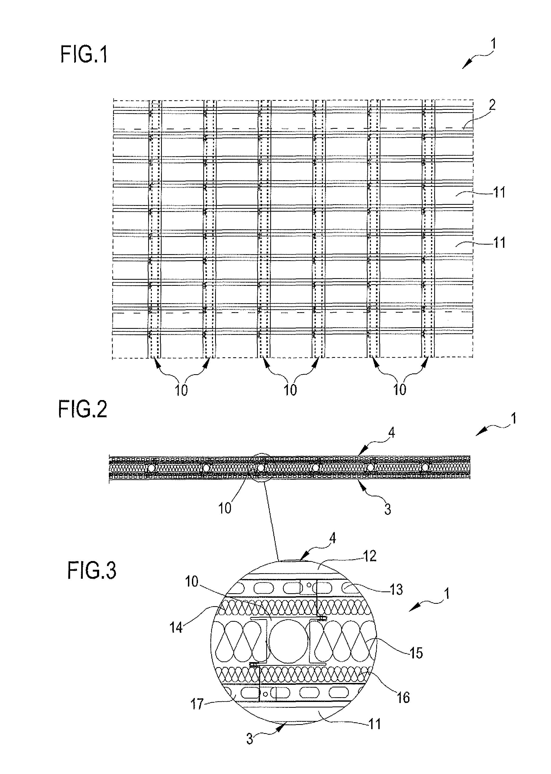
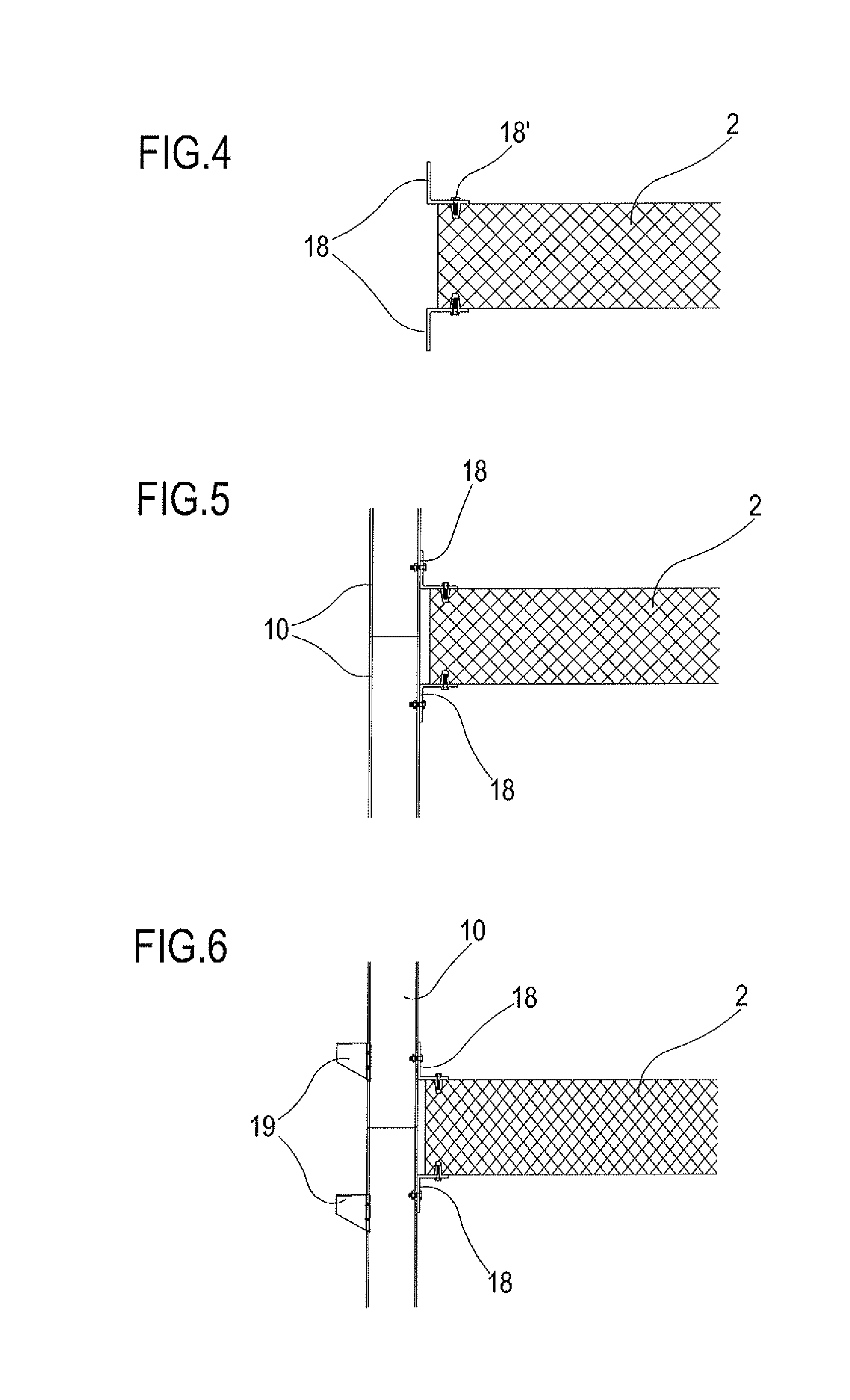
[0061]Reference numeral 101 denotes in its entirety a support framework for building casings 200. The framework 101 of the present invention can be used for the construction of building casings 200 which will go to define the lateral surface of a building structure 300 or which can be used for the construction of building casings 200 which will go to clad the pre-existing perimeter walls of a building structure 300; the framework 101 object of the present invention is used in the construction industry for the production and / or cladding alone of dwellings and / or industrial buildings.

[0062]As visible for example in FIGS. 35 and 40, the framework 101 comprises a is plurality of uprights 110 each of which extends along a first prevalent development direction (each upright extends between a first and a second longitudinal end) and is intended in use to extend vertically between at least a first floor deck and / or base 102 and a second floor deck and / or base 102 of a building structure 300...


PUM


Abstract

A support framework (101) for building casings (200) using pultruded uprights, a building casing (200) and a building structure (300). Also described are a process for realizing and installation of the building structure (300), as well as manufacturing processes of the various components of the framework.

Description

FIELD OF THE INVENTION[0001]The present invention relates to a support framework for building casings, a building casing and a dwelling structure comprising said framework. The present invention further concerns a process of realization of the building structure. The present invention can be applied both in the dwelling building sector and in the industrial building sector.STATE OF THE ART[0002]In the building sector, buildings are known that originate from a bearing structure—mainly comprising columns, beams and floors—which is closed internally of a cladding able to separate the inside of the building from the external environment. The casing is essentially constituted by a framework constrained to the bearing structure of the building and which stably engages the perimeter walls thereof (confining walls). The framework essentially defines a connecting element between the bearing structure and the perimeter walls and does not in fact constitute a structural element of the building...

Claims


Application Information

Patent Timeline
IPC IPC(8): E04B2/58E04B1/24E04B1/41
CPCE04B2/58E04B1/24E04B1/40F24F7/02E04D13/17E04C2003/0439E04C2003/0452E04C2003/0465E04B1/28E04B1/4178E04B1/7637E04B1/7612E04B2/90E04B1/7662E04B2001/745E04B1/388E04B2/88E04B1/003E04B2001/2415E04B2001/2445E04B2001/2448E04B1/762
Inventor BERTOLDINI, AUGUSTOBRANCA, ALFONSO
Owner TOP GLASS EU
Learn More