Asymmetric multirotor helicopter

a multi-rotor helicopter and asymmetric technology, applied in the field of helicopters, can solve the problems of disadvantage and complex multi-rotor vehicles, and achieve the effect of increasing the speed of the front propulsion system and decreasing the speed of the rear propulsion system

Active Publication Date: 2015-10-01
KERETH YEFIM
View PDF19 Cites 41 Cited by
  • Summary
  • Abstract
  • Description
  • Claims
  • Application Information

AI Technical Summary

Benefits of technology

[0027]forward tilt is controlled by the elevator by increasing the speed of the rear propulsion system while decreasing the speed of the front propulsion system;
[0028]rear tilt is controlled by the elevator by increasing the speed of the front propulsion system while decreasing the speed of the rear propulsion systems;
[0029]left tilt is controlled by the aileron by increasing the speed of the right propulsion system while decreasing the speed of the left propulsion system;
[0030]right tilt is controll

Problems solved by technology

However, at high lift capacity, the complexity of the multirotor vehicle, because of the higher number of high power propulsion systems and because of the significantly

Method used


Image

  • Asymmetric multirotor helicopter
  • Asymmetric multirotor helicopter
  • Asymmetric multirotor helicopter

Examples


Embodiment Construction

[0036]The above description is given by way of example, and not limitation. Given the above disclosure, one skilled in the art could devise variations that are within the scope and spirit of the invention disclosed herein. Further, the various features of the embodiments disclosed herein can be used alone, or in varying combinations with each other and are not intended to be limited to the specific combination described herein. Thus, the scope of the claims is not to be limited by the illustrated embodiments.

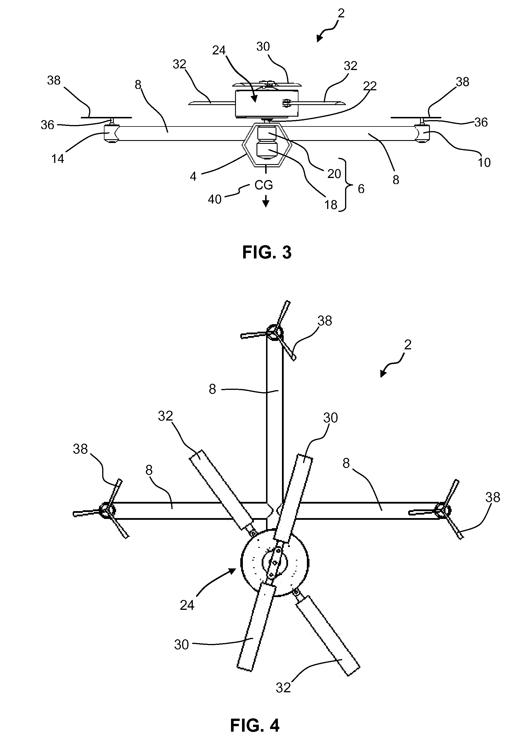
[0037]FIGS. 1 to 4 are general representations of a single main rotor helicopter with a multirotor structure and flight control of “+” configuration shown generally as 2 comprising a main structure 4 that carries a main propulsion system 6 and having three secondary arms 8, each adapted to carry one of three secondary propulsion systems 10, 12 and 14. The main propulsion system 6 is a high-power system and it is significantly more powerful than the three secondary propulsion sys...


PUM


Abstract

An asymmetric multirotor helicopter has a structure supporting at least one main and two secondary propulsion systems. A flight control unit controls the helicopter by varying the relative speed of each of the main and secondary propulsion systems. Each main propulsion system includes at least one main motor drive and a main drive shaft that carries and propels a main differential contra-rotating transmission configured to share the power provided by the main drive shaft with two contra-rotating output shafts. Each secondary propulsion system includes at least one secondary motor drive and a secondary drive shaft that carries and propels respective secondary propulsion blades. The two contra-rotating output shafts support and propel for mutually contra-rotation motion two sets of main propulsion blades. The main drive shaft rotates in the same direction as one of the secondary drive shafts and at least one secondary drive shaft rotates in an opposite direction.

Description

CROSS-REFERENCE TO RELATED APPLICATIONS[0001]The present application claims priority to Israeli Application No 231811 filed on Mar. 16, 2014.STATEMENT RE: FEDERALLY SPONSORED RESEARCH / DEVELOPMENT[0002]Not ApplicableBACKGROUND[0003]1. Field of the Invention[0004]This invention relates to a helicopter with a multirotor structure and flight control.[0005]2. Background of the Invention[0006]The following definition for a multirotor aerial vehicle is:[0007]“A multirotor or multicopter is a rotorcraft with more than two rotors. Multirotors often use fixed-pitch blades, whose rotor pitch does not vary as the blades rotate; control of vehicle motion is achieved by varying the relative speed of each rotor to change the thrust and torque produced by each. Due to their ease of both construction and control, multirotor aircraft are frequently used in model and radio control aircraft projects in which the names quadcopter, hexacopter and octocopter are frequently used to refer to 4-, 6- and 8-ro...

Claims


Application Information

Patent Timeline
IPC IPC(8): B64C27/10B64C27/12B64C27/82B64C27/32
CPCB64C27/10B64C27/32B64C2027/8227B64C27/82B64C27/12B64C27/08B64C39/024B64U10/13B64U30/20
Inventor KERETH, YEFIM
Owner KERETH YEFIM
Why Eureka
Try Eureka