Facility and method for producing containers

a technology of container production and production method, which is applied in the field of container production method, to achieve the effect of reducing preform loss, ensuring the functional reliability of further processing steps, and ensuring product quality

Active Publication Date: 2015-10-01
KRONES AG
View PDF3 Cites 4 Cited by
  • Summary
  • Abstract
  • Description
  • Claims
  • Application Information

AI Technical Summary

Benefits of technology

[0012]The advantage achieved as a result of this lies in the fact that, by suspending the synchronisation, the container production device can continue to operate independently of the treatment device and the fault in the treatment device can be eliminated while the container production device continues to operate. There is therefore no need for the container production device to be run up again when a fault has occurred in one of the treatment devices. In a container production device comprising a blow moulding device and an upstream heating device, lower preform losses are achieved as a result, particularly in the case of brief faults. If the fault elimination in the treatment device takes less than the time necessary for the container production device to be run up again, then a shortening of the fault elimination is achieved, along with a longer production time and a higher degree of efficiency.
[0034]The filling device, the labelling device and / or the closing device may be configured in such a way that they can be run up in synchronisation with one another. As an alternative, these devices may also be configured in such a way that they can be run up individually and then synchronised with one another. By virtue of this configuration, it is particularly easy in terms of controlling to run up and synchronise the treatment device with the container production device.

Problems solved by technology

A fault is understood here to mean in particular faults that have already occurred; however, a reaction to faults occurring in future would be conceivable, for example when the user recognises that a certain machine behaviour or a certain actual state of the machine or of the processing will lead to a fault in the future.

Method used


Image

  • Facility and method for producing containers
  • Facility and method for producing containers
  • Facility and method for producing containers

Examples


Embodiment Construction

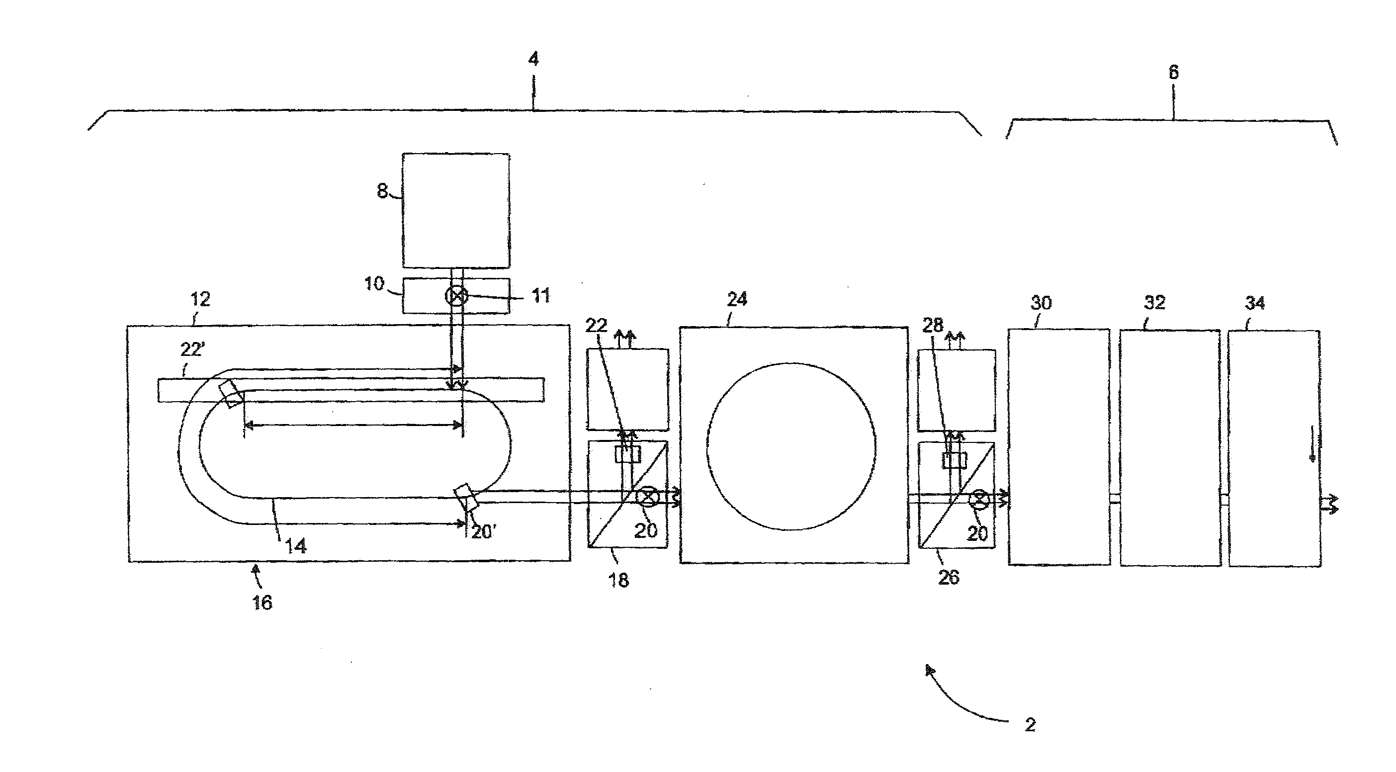
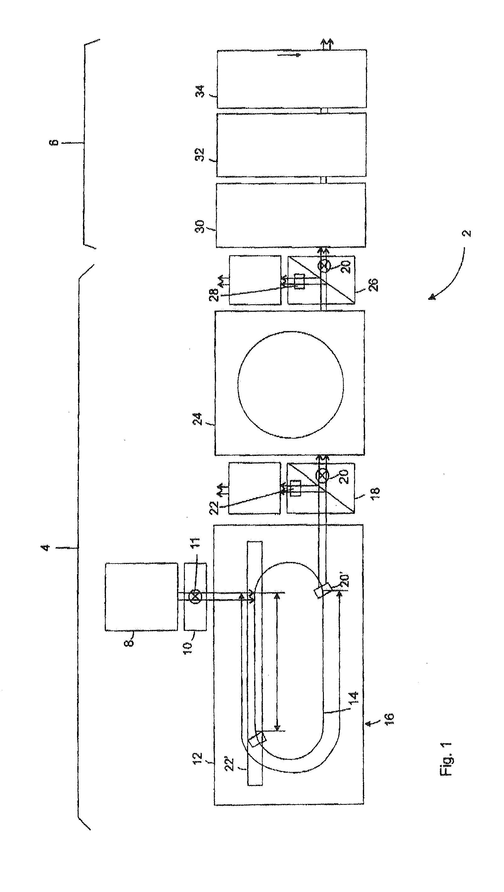
[0038]The embodiment shown in FIG. 1 is a facility 2 for producing and further treating containers. The facility 2 comprises the container production device 4 shown in the left-hand part of FIG. 1 and the container processing device 6 shown in the right-hand part of FIG. 1. The container production device 4 comprises a storage device 8, a stock supply device 10 and a heating device 12 with a preform transport means 14 arranged therein and a heating region 16. Also provided is a conveying device 18 for conveying preforms heated in the heating device 12 into a downstream blow moulding machine 24, the blow moulding machine 24 (container transformation device), a preform discharging device 22 for discharged preforms, which is controllably and operatively coupled to the conveying device 18, a transfer device 26 to the filler (container processing device 6), a discharging device 28 for blow-moulded containers, which is controllably and preferably operatively coupled to the conveying devic...


PUM

PropertyMeasurementUnit
timeaaaaaaaaaa
timeaaaaaaaaaa
temperatureaaaaaaaaaa

Abstract

A facility for processing containers includes a container production device and at least one processing device disposed downstream from the container production device, for further processing the containers. The container production device is synchronized with the processing device during regular operation. However, upon recognition of a malfunction in the processing device, synchronization of the container production device with the processing device can be at least temporarily canceled. Also provided is a method for remedying malfunctions in a facility, in which a container production device is synchronized with a processing device during regular operation, according to which, synchronization between the container production device and the processing device is at least temporarily canceled upon recognition of a malfunction in the treatment device.

Description

CROSS REFERENCE TO RELATED APPLICATIONS[0001]This application is a divisional of U.S. application Ser. No. 12 / 989,787, filed Oct. 26, 2010, which application in turn is a 371 of PCT / EP2009 / 055099, filed Apr. 28, 2009, which in turn claims priority from German Application 10 2008 021 527.9, filed Apr. 30, 2008, the contents of which are incorporated herein by reference, in their entireties.BACKGROUND OF THE INVENTION[0002]The present invention relates to a method for eliminating faults in a facility for producing and treating or processing containers having a container production device for producing containers and at least one treatment device for further processing the containers, and to a facility having a container production device and at least one treatment device for further processing the containers. Such facilities are used in particular for the production and immediately subsequent treatment or processing of containers.[0003]In the prior art, methods and facilities are know...

Claims


Application Information

Patent Timeline
Patent Type & Authority Applications(United States)
IPC IPC(8): B29C49/78B29C49/42B29C49/64
CPCB29C49/78B29C49/6409B29L2031/712B29C2949/78554B29C2949/7821B29C49/4205B29C49/06B29C49/42B29K2105/26B29L2031/7158B67C2003/227B67C7/0013B29C49/42109B29C49/42362B29C49/42378B29C49/4238B29C49/42808B29C2949/0715
Inventor HAHN, WOLFGANG
Owner KRONES AG
Why Eureka
Try Eureka