
Shower door assembly for fast assembling and adjustment

a technology for shower doors and assembly parts, applied in the field of shower door assembly, can solve the problems of not being able to quickly open or close the shower door, requiring at least two people to cooperate in the operation, and being undesirable to consumers, and achieve the effect of fast assembly and adjustment, and lateral width of the elastic elemen

Inactive Publication Date: 2015-10-01
IDEAL SANITARY WARE CO LTD
View PDF0 Cites 5 Cited by
  • Summary
  • Abstract
  • Description
  • Claims
  • Application Information

AI Technical Summary

Benefits of technology

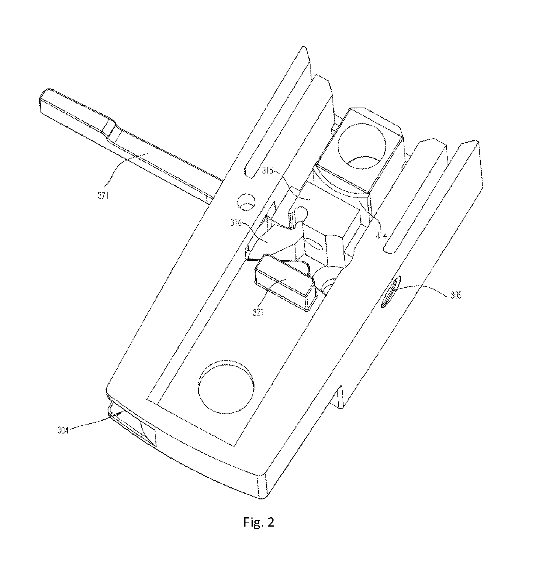
The present invention is a shower door assembly that includes a cam mechanism and a sliding element in the first cavity, which pushes the pressing element towards the blocking element to reduce the curvature of the elastic element. The locking device is engaged with the adjustment device to secure the position of the shower door. The assembly has the advantages of fast assembling and adjustment with minimum force, while also being able to lock and release. In one embodiment, a spacer element is added to prevent deformation of the elastic element. The pressing element has platforms to prevent turnover during movement. The surface of the adjustment device that engages the elastic element has teeth to enhance the engagement. In another embodiment, the assembly includes a locking mechanism for preventing accidental disengagement of the adjustment device. Overall, the shower door assembly provides a reliable and secure solution for adjusting and locking the shower door.

Problems solved by technology

Therefore, if mounted completely along the wall surface, the doors may not be smoothly opened or closed.
However, in one aspect, the drilling operation requires at least two people to cooperate and is very time-consuming.
In another aspect, the drilling may inadvertently cause damages to the surfaces of the frames generally made of aluminum materials, which is undesirable to consumers.

Method used


Image

  • Shower door assembly for fast assembling and adjustment
  • Shower door assembly for fast assembling and adjustment
  • Shower door assembly for fast assembling and adjustment

Examples


Embodiment Construction

[0036]The invention will now be described in more detail in reference to preferable examples in conjugation with the accompanied drawings.

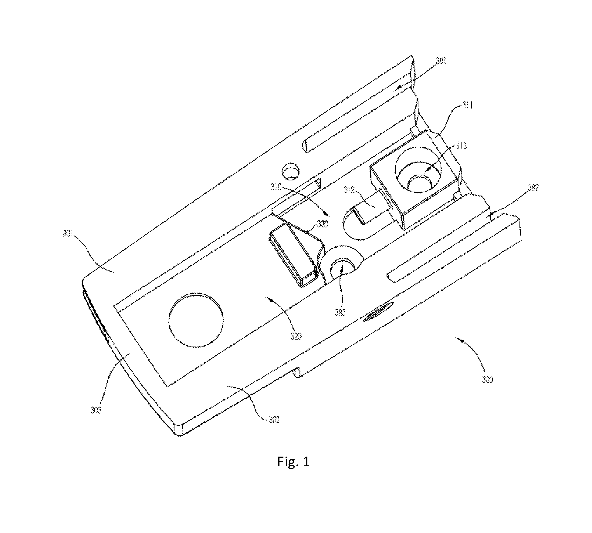
[0037]FIG. 1 partially shows a locking device 300 according to one embodiment of the invention. The locking device 300 is substantially rectangular in shape. Two opposite sides 301, 302 and a bottom side 303 jointly define an open internal space. The internal space comprises a first cavity 310 and a second cavity 320. The second cavity 320 has a less depth than that of the first cavity 310. An interface between the first and second cavities 310, 320 has at least a part forming an inclined surface 330 projecting toward the first cavity 310.

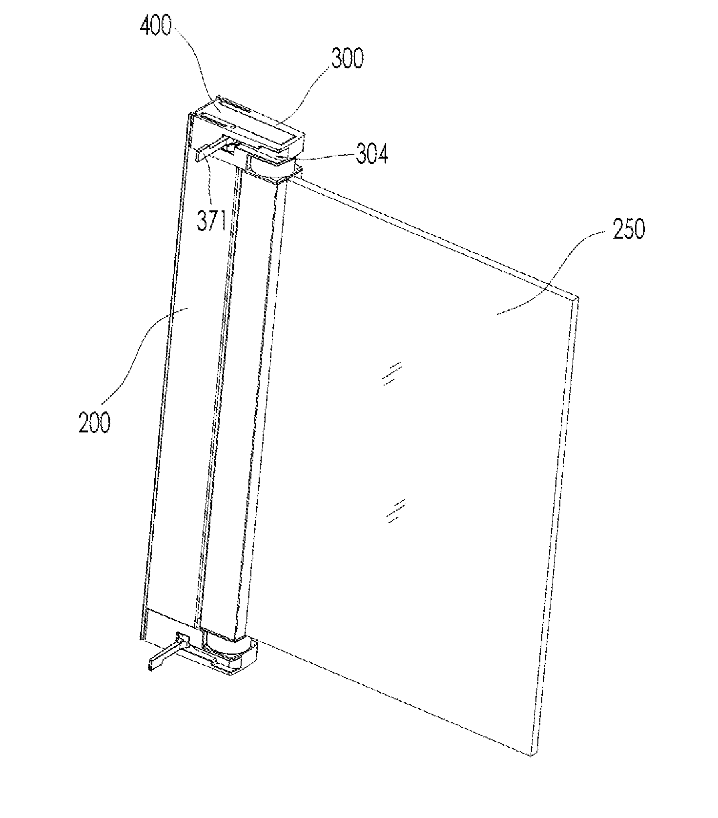
[0038]The locking device 300 is coupled to a movable frame 200 (see FIG. 9) at at least two linkage points 313, 383, such that the locking device 300 will not rotate around the movable frame 200.

[0039]In FIG. 1, a blocking element 311 is provided within the first cavity 310 at an end that is away from the bottom ...


PUM


Abstract

A shower door assembly with at least one adjustment assembly has an adjustment device and a locking device. The locking device includes a blocking element, a pressing element and an elastic element between the blocking element and the pressing element. The elastic element is arc-shaped when unlocked. An inclined surface projects to the blocking element. The curvature of the elastic element is thus reduced until it engages with the adjustment device. A driving device includes a cam mechanism and a sliding element having one end in contact with the pressing element and the other end sliding along with the inclined surface when driven by the cam mechanism so as to push the pressing element toward the blocking element, and thus reduce the curvature of the arc-shaped elastic element until the elastic element is engaged with the adjustment device.

Description

FIELD OF THE INVENTION[0001]The present invention relates to shower door assembly, and in particular, to adjustment assembly used therein which achieves fast assembling and adjustment.BACKGROUND OF THE INVENTION[0002]Doors used for shower enclosure are often mounted against wall surfaces and the doors thus mounted are kept as vertical as possible. However, the wall surfaces of buildings are often not exactly vertical, for example, titled toward outside / inside by an angle. Therefore, if mounted completely along the wall surface, the doors may not be smoothly opened or closed. In this regard, it is necessary to adjust the distances between the top / bottom end of a door and a wall surface so as to keep the door in a vertical position.[0003]To achieve this adjustment, a door assembly usually comprises a stationary frame to be attached to a wall surface, and a movable frame connected with a door panel, such as a glass door panel. The stationary frame is firstly attached to the wall surfac...

Claims


Application Information

Patent Timeline
IPC IPC(8): A47K3/34
CPCA47K3/34A47K3/36A47K2003/307A47K3/00E05D11/0054E05D7/081E05Y2201/11E05Y2600/12E05Y2600/14E05Y2600/312E05Y2600/324E05Y2600/502E05Y2600/522E05Y2600/56E05Y2600/62E05Y2900/132
Inventor WEI, WUXIANG
Owner IDEAL SANITARY WARE CO LTD
Learn More