Surface treating head

Inactive Publication Date: 2015-09-24
DYSON TECH LTD
View PDF4 Cites 4 Cited by
  • Summary
  • Abstract
  • Description
  • Claims
  • Application Information

AI Technical Summary

Benefits of technology

The patent is for a surface treating head that can be adjusted for different floor surfaces and can easily move around the floor to ensure optimal cleaning performance. The head has two bodies that can be positioned in different ways, which allows the outer or inner aperture to be closer to the floor surface for better suction. The head can also have floor engaging wheels to improve its mobility and to maintain a certain distance between the floor surface and the head for better cleaning performance. The technical effect of this patent is to provide a more versatile and adaptable surface treating head for floor cleaning.

Problems solved by technology

However, on a hard floor surface, the working edges would slide along the surface of the floor with barely any effect on loosening the dust and dirt to be picked up, and would therefore act to worsen the pick-up performance.
Unfortunately, movable brushes within the surface treating head can give rise to a decrease in suction if air is able to pass through any gaps formed between the brushes and the body of the surface treating head.
Having brushes that move up and down can also disrupt the seal and can reduce the suction generated at the floor surface.

Method used


Image

  • Surface treating head
  • Surface treating head
  • Surface treating head

Examples


Embodiment Construction

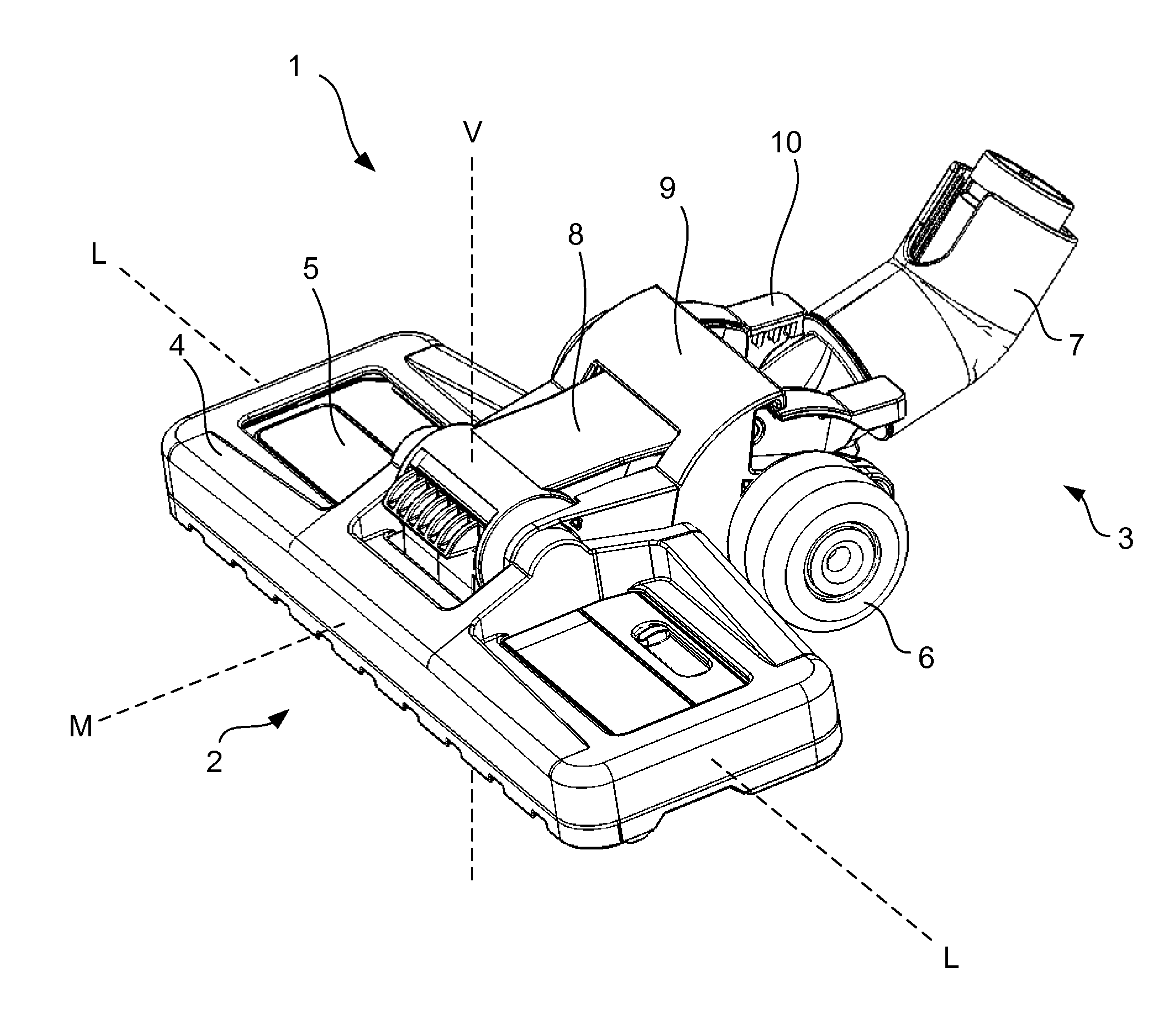
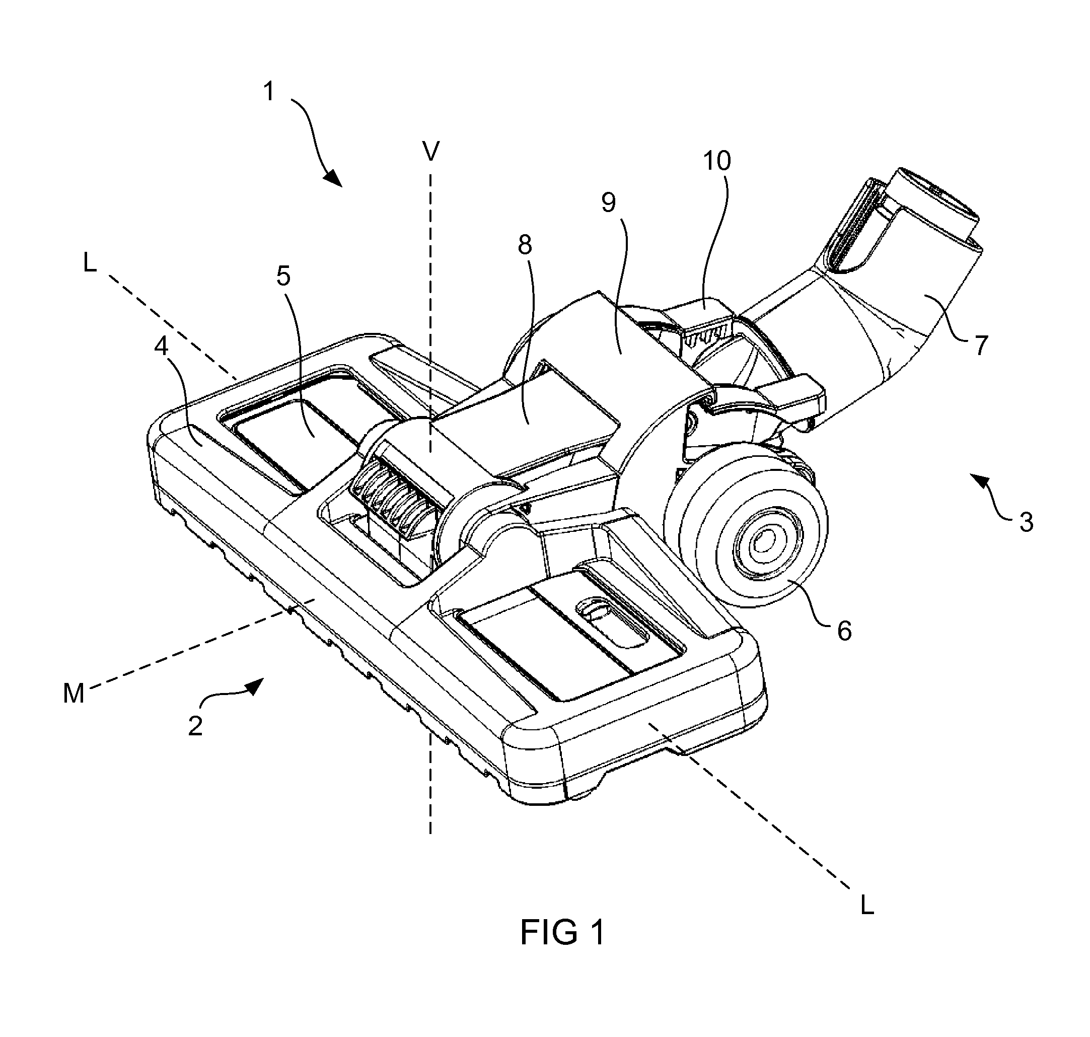
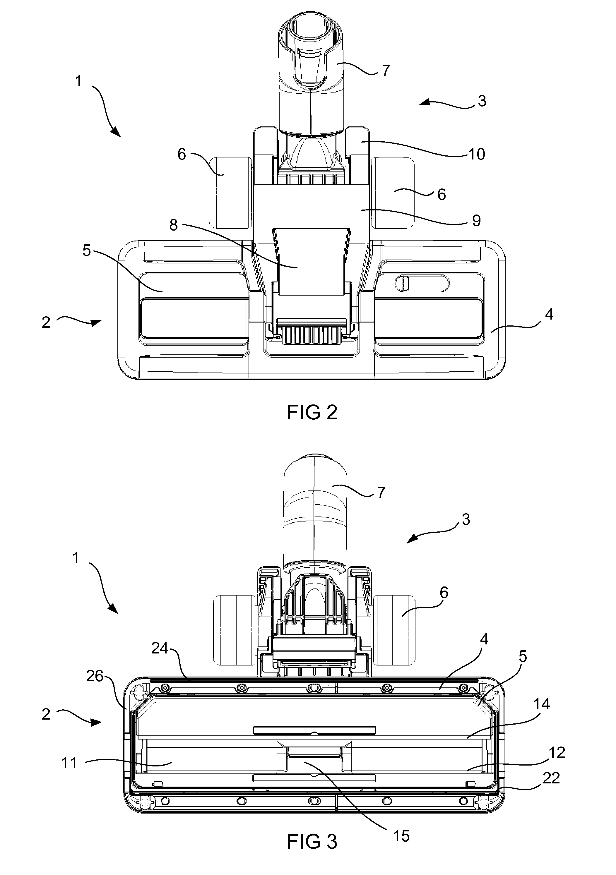
[0027]FIGS. 1, 2 and 3 show a surface treating head 1. The surface treating head 1 comprises a main body 2 and a rolling support 3. The main body 2 comprises a first body which is a soleplate body 5, a support body 4 that surrounds the soleplate body 5. The support body 4 and the soleplate body 5 are moveable relative to one another in a substantially vertical direction, i.e. substantially parallel to axis V. The rolling support 3 comprises wheels 6 and a swivel duct 7. The swivel duct 7 allows the surface treating head 1 to be attached to a vacuum cleaner, for example by way of a wand attachment in the case of a cylinder- or canister-style vacuum cleaner. The swivel duct 7 is in fluid connection with the main body 2, and in particular with the soleplate body 5, by way of duct 8. Lever 9 and catch 10 are provided on the upper side of the surface treating head 1 and which can be used to select and de-select different relative positions of the soleplate body 5 and the support body 4. ...


PUM


Abstract

A surface treating head comprising a first body defining an inner aperture, and a support body defining an outer aperture, the outer aperture surrounding the inner aperture, and the support body being moveable relative to the first body to allow for relative movement between the inner and outer apertures in a substantially vertical direction, wherein the surface treating head further comprises a bellow seal provided between the first body and the support body that maintains a substantially airtight seal between the first body and support body irrespective of their relative positions and movements.

Description

REFERENCE TO RELATED APPLICATIONS[0001]This application claims the priority of United Kingdom Application No. 1405063.7, filed Mar. 21, 2014, the entire contents of which are incorporated herein by reference.FIELD OF THE INVENTION[0002]The present invention relates to a surface treating head.BACKGROUND OF THE INVENTION[0003]Surface treating appliances such as vacuum cleaners are usually provided with one or more surface treating heads, often referred to as a cleaner head. It is common for cleaner heads to be able to be manipulated between different “modes” of use. The different modes can, for example, allow for more effective cleaning by the surface treating head on different types of floor surface, such as carpeted or hard floors.[0004]One example of the different modes that can be provided in a surface treating head is to have a set of brushes that can be raised or lowered with respect to a soleplate. In a raised position, the soleplate may be positioned lower than the brushes, an...

Claims


Application Information

Patent Timeline
IPC IPC(8): A47L9/02A47L9/00A47L9/24A47L9/04
CPCA47L9/02A47L9/242A47L9/009A47L9/0477A47L9/0666A47L11/30A47L9/04A47L9/06
Inventor GRAY, JONATHAN JAMESCROSS, SIMON PETER
Owner DYSON TECH LTD
Why Eureka
Try Eureka