Multichannel wireless communication system, base station, and method for using channel
a wireless communication system and wireless communication technology, applied in wireless communication services, wireless communication services, electrical equipment, etc., can solve problems such as problems such as the lack of allocatable frequencies, and achieve the effect of high-speed and robust communication
- Summary
- Abstract
- Description
- Claims
- Application Information
AI Technical Summary
Benefits of technology
Problems solved by technology
Method used
Image

Examples
example 1
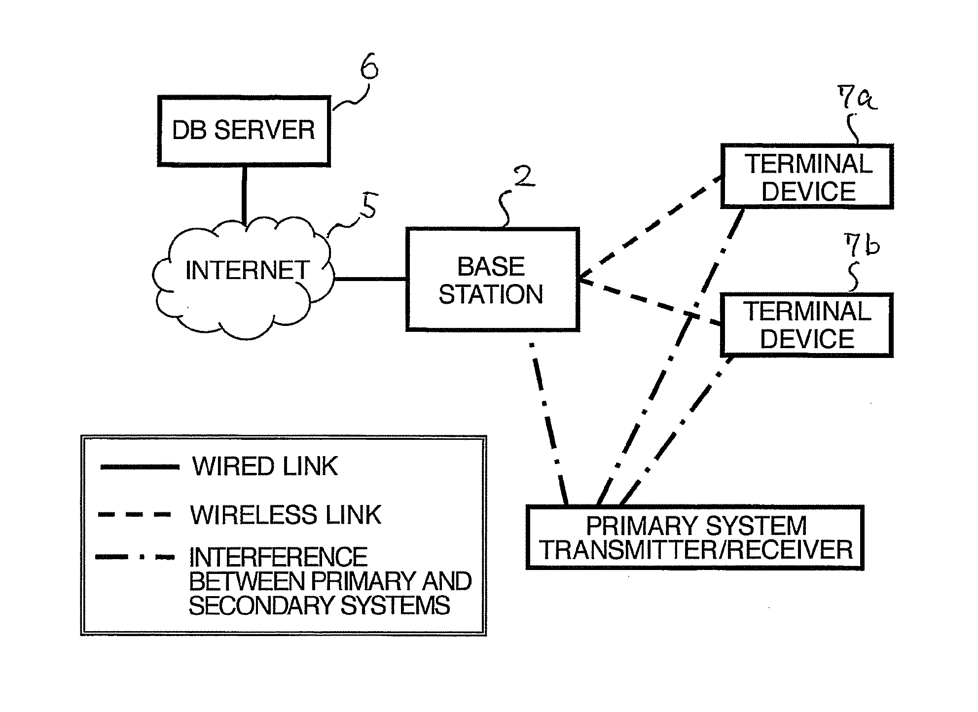
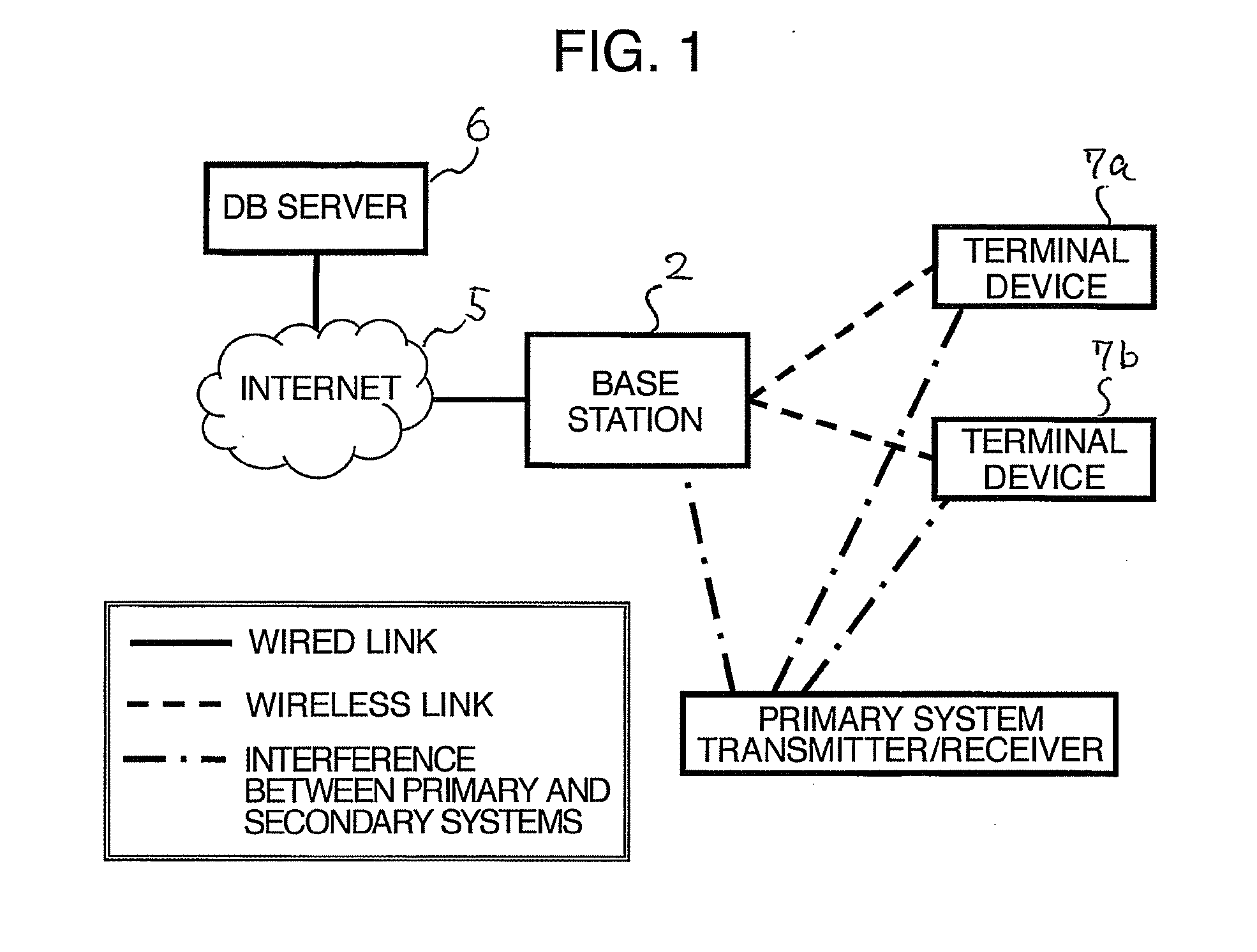
[0057]FIG. 1 illustrates an exemplary entire structure of a multi-channel wireless communication system according to Example 1. The multi-channel wireless communication system is assumed to be applied (revised) to the 802.22, and has the same basic structure as ever. However, BS 2 and CPE 7a, 7b have the different structures from conventional ones, such as simultaneous transmission / reception in a plurality of channels. CPE 7a and 7b are collectively called CPE 7.
[0058]FIG. 4 is a schematic diagram illustrating communication between BS 2 and CPE 7 in the multi-channel wireless communication system according to Example 1. BS 2 has a plurality of wireless communication units (BS-CHU) 13a, 13b, and a channel unit control manager (CHU-M) 14 for controlling the BS-CHUs. Inter-unit I / F 16 and 15 are provided between BS-CHU 13 and CHU-M 14 in order to connect them. CHU-M 14 also includes an Internet connection I / F 17 for connecting to the Internet (WAN).
[0059]BS-CHU 13 has a capability of t...
example 2
[0129]FIG. 11 is a functional block diagram of BS 120 in a multi-channel wireless communication system according to Example 2. Additionally, FIG. 12 is a functional block diagram of CPE 170 in the multi-channel wireless communication system according to Example 2. In the present example, detailed mounting not described in Example 1 will be described, and unless otherwise noted, the structure and functions according to Example 1 will be employed. FIG. 11 and FIG. 12 express hardware in more detail than FIG. 4.
[0130]As illustrated in FIG. 11, BS 120 includes a plurality of BS-CHUs 130a, 130b (collectively denoted as 130), a CHU-M 124, and a sensing unit 125.
[0131]CHU-M 124 includes the channel allocation manager (CAM) 41 for allocating operating channels to individual BS-CHUs 130, the CPE management unit 42 for holding information on CPE 170 connected to BS 2 and managing states of CPE, a management information processing unit (MIB) 43, a DB access control unit 44, a communication dat...
example 3
[0190]A scheme for evenly sharing channels, which has not been described according to Examples 1 and 2, will be described according to the present example. The structure and functions according to Example 1 will be employed.
[0191]BS 220 according to Example 1 explicitly includes a self-co-existence function unit 47. The self-co-existence function unit 47 additionally has a channel negotiation function in addition to co-existence by conventional frame contention or the like. Channel negotiation eliminates a situation in which BS which earlier starts operation occupies a plurality of channels and BS which is activated later cannot use any channel.
[0192]Four new messages including channel release request (CHN-REQ), channel release time notification (CHN-RSP), channel release time acknowledgement response (CHN-ACK) and channel release completion (CHN-CPLT) are defined in the MAC layer in order to realize the channel negotiation function.
[0193]FIG. 15 is a flowchart of an operating chann...
PUM
 Abstract
Description
Claims
Application Information
 - R&D
- Intellectual Property
- Life Sciences
- Materials
- Tech Scout
- Unparalleled Data Quality
- Higher Quality Content
- 60% Fewer Hallucinations
Browse by: Latest US Patents, China's latest patents, Technical Efficacy Thesaurus, Application Domain, Technology Topic, Popular Technical Reports.
© 2025 PatSnap. All rights reserved.Legal|Privacy policy|Modern Slavery Act Transparency Statement|Sitemap|About US| Contact US: help@patsnap.com