
Motorcycle helmet with increased visibility

a technology of motorcycle helmet and helmet body, applied in the field of motorcycle helmet, can solve the problems of reduced visibility to other drivers, reduced visibility of motorcycles, and reduced visibility of motorcycles, and achieve the effect of increasing visibility

Inactive Publication Date: 2015-09-10
BECKERS JAMES RANDALL +4
View PDF13 Cites 17 Cited by
  • Summary
  • Abstract
  • Description
  • Claims
  • Application Information

AI Technical Summary

Benefits of technology

The patent is for a motorcycle helmet with LED lights that can be directed towards an object to make the rider and motorcycle more visible to other drivers. The LEDs can be mounted on the front of the helmet or in the rear to function as additional brake lights and turn signals. The helmet can also have a cable or wireless system to control the LEDs. The LEDs can also be placed on the sides of the helmet to increase visibility from the side. Overall, the technology improves safety for motorcyclists by enhancing visibility for other drivers.

Problems solved by technology

Motorcycles are small vehicles that carry limited road illumination capability and have reduced visibility to other drivers.
The visibility of a motorcycle is particularly low to automobile drivers entering a road that the motorcycle is traveling where the auto pulls onto the road from a side road or street or turns across the road in front of the motorcycle.
This appears to be due to the automobile driver typically looking for other automobiles and not being accustomed to the low visibility of motorcycle.
Another frequent motorcycle accident scenario is due to the poor rear visibility of a motorcyclist when a larger vehicle is approaching from the rear.

Method used


Image

  • Motorcycle helmet with increased visibility
  • Motorcycle helmet with increased visibility
  • Motorcycle helmet with increased visibility

Examples


Embodiment Construction

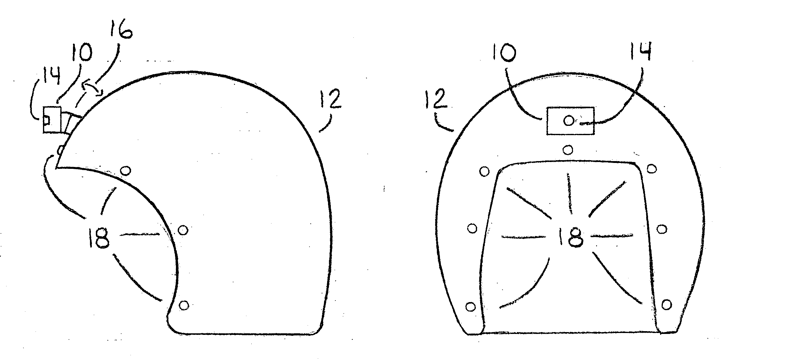
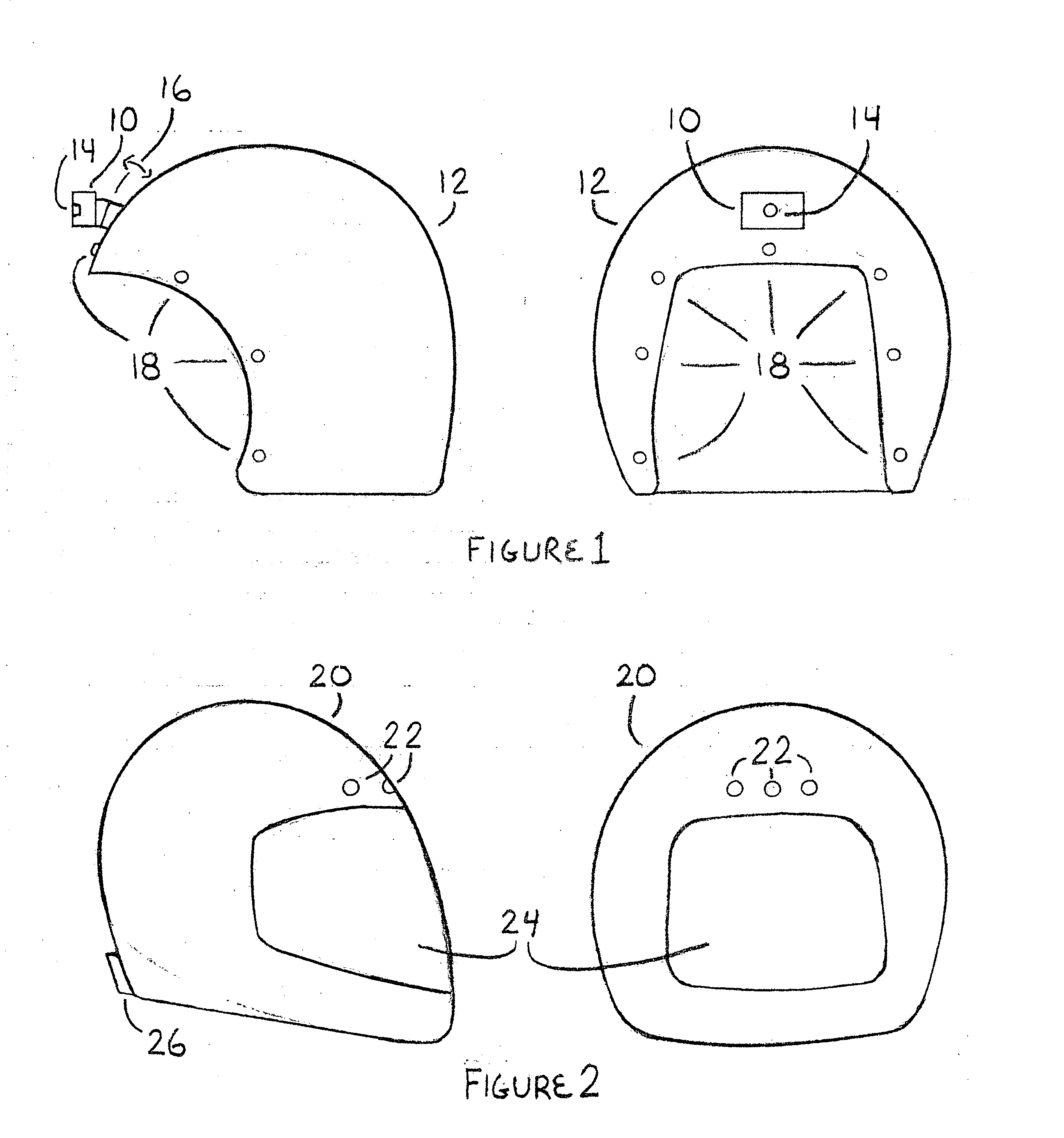
[0027]The visibility and illumination features of a motorcycle rider can be improved by an embodiment including a light module 10 mounted on a front side of a helmet 12, such as an open face helmet depicted in FIG. 1. The module 10 includes one or more white light type light emitting diodes (LEDs) 14 that point away from the front of the helmet 12 in a direction that a rider is looking and project one or more white light beams that can be pointed by the helmet wearer. The module 10 includes batteries, an on / off switch and electronic components (not shown) needed to power the LED and is, thus, self contained. The module 10 may even contain LEDs that allow the beam shape and brightness to be changed. The module 10 may be attached to the helmet 12 by a hinged bracket 16 with a friction hinge that allows the vertical angle of the beam to be adjusted / pivoted (see arrows) to align with a rider's preference for the vertical axis of where the beam is pointed. The bracket 16 may be secured t...


PUM


Abstract

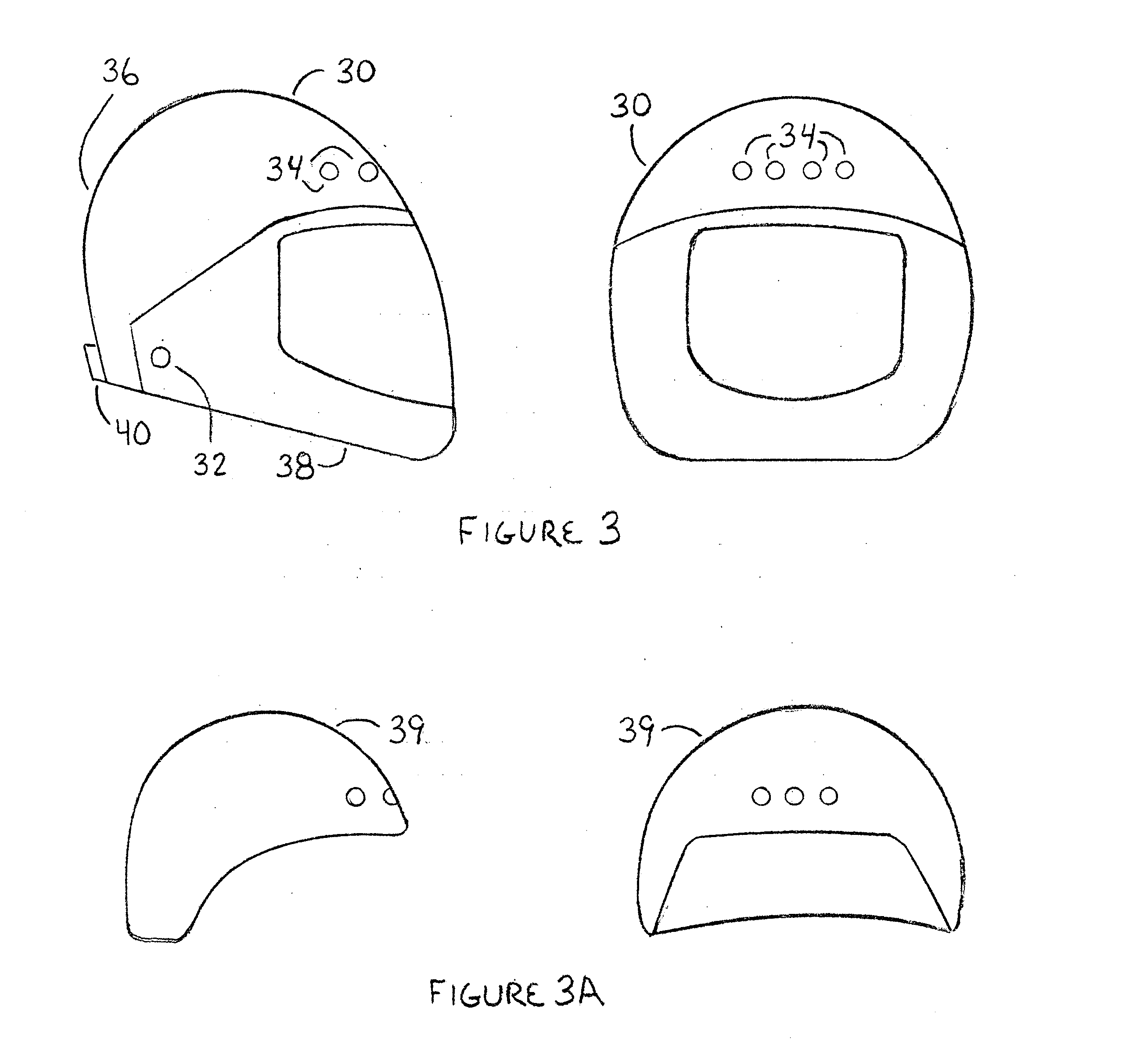
A motorcycle helmet that includes one or more white light type beam forming LEDs (LEDs with lenses that form a beam) mounted in the front of the helmet, such as the helmet forehead area. The LEDs may function as a headlight that may supplement the motorcycle headlight. The beam(s) projected by the LEDS can be steered or aimed at an object by the helmet wearer and may help the rider and motorcycle be more visible to oncoming vehicles or vehicles entering from a side road while at the same time having a downward pointing aspect and a power hat does not create glare for other drivers. The LEDS may be in a self contained module mounted on the outside of the helmet. The LEDs may be mounted or embedded in the outer shell of the helmet with the batteries and electronics being inside the shell and within the foam type compressible inner shell. The batteries and electronics may also be within the helmet neck roll near the bottom rim of the helmet. LEDs, red and yellow or orange, may also be located in the rear of the helmet and function as additional brake lights and turn signal lights. A cable or wireless system may be used to send brake turn signal and headlight signals to the helmet to control the LEDs.

Description

FIELD[0001]A motorcycle helmet with increased visibility and improved road illumination provided by a front facing beam type light that can act as a point-able headlight allowing the wearer to point a light beam at an object in front of the motorcycle, such as an edge of a road or a vehicle on a side road.DESCRIPTION OF THE RELATED ART[0002]Motorcycles are small vehicles that carry limited road illumination capability and have reduced visibility to other drivers.[0003]The visibility of a motorcycle is particularly low to automobile drivers entering a road that the motorcycle is traveling where the auto pulls onto the road from a side road or street or turns across the road in front of the motorcycle. This appears to be due to the automobile driver typically looking for other automobiles and not being accustomed to the low visibility of motorcycle. What is needed is to increase visibility of a motorcycle to drivers of automobiles and other larger vehicles.[0004]Because a motorcycle h...

Claims


Application Information

Patent Timeline
Patent Type & Authority Applications(United States)
IPC IPC(8): A42B3/04
CPCA42B3/0433A42B3/0446A42B3/044
Inventor BECKERS, JAMES RANDALLPIEPMEIER, BRAD BIONEABY, JEFFREY LYNNDUKE, WILLIAM HARBINGRIFFIN, CHARLES DURWARD
Owner BECKERS JAMES RANDALL
Learn More