
Split septum assembly for an intravenous injection site

a technology of intravenous injection and septum, which is applied in the field of intravenous injection sites, can solve the problems of clotting of the blood and occlusion of the injection site, and undesirable retraction of the cannula or needle, so as to prevent proximal leakage of fluids

Active Publication Date: 2015-08-13
NEXUS MEDICAL LLC
View PDF3 Cites 31 Cited by
  • Summary
  • Abstract
  • Description
  • Claims
  • Application Information

AI Technical Summary

Benefits of technology

The invention is a septum that helps prevent fluid from leaking through a device or holder that it is used with. The septum includes a cylindrical body with a flange around its outside. When the septum is used, the flange is compressed to create a double hermetic seal, ensuring that fluid cannot leak through or around the holder. This improves the reliability and security of the device.

Problems solved by technology

Blood reflux potentially leads to clotting of the blood and occlusion of the injection site.
Such intravenous devices present several problems.
In a first problem, a fluid passageway fluid connected to the septum is generally axially straight, especially proximate the septum.
This retraction of the cannula or needle is undesirable, as it can introduce bacteria into the septum.
A second problem is a size of the form factor of intravenous devices.
However, simply making a smaller form factor with the same general structure as standard-sized form factors presents new problems.
As the form factor becomes smaller, and consequently the septum and surrounding housing becomes smaller, it becomes more difficult for the septum to seal against undesired fluid flow, especially with use of the larger-diameter cannula (as compared to the needle).
Another issue with making the form factor smaller is that the priming volume is reduced.

Method used


Image

  • Split septum assembly for an intravenous injection site
  • Split septum assembly for an intravenous injection site
  • Split septum assembly for an intravenous injection site

Examples


Embodiment Construction

[0031]The following detailed description of embodiments of the invention references the accompanying drawings that illustrate specific embodiments in which the invention can be practiced. The embodiments are intended to describe aspects of the invention in sufficient detail to enable those skilled in the art to practice the invention. Other embodiments can be utilized and changes can be made without departing from the scope of the present invention. The following detailed description is, therefore, not to be taken in a limiting sense. The scope of the invention is defined only by the appended claims, along with the full scope of equivalents to which such claims are entitled.

[0032]In this description, references to “one embodiment,”“an embodiment,” or “embodiments” mean that the feature or features being referred to are included in at least one embodiment of the technology. Separate references to “one embodiment,”“an embodiment,” or “embodiments” in this description do not necessaril...


PUM


Abstract

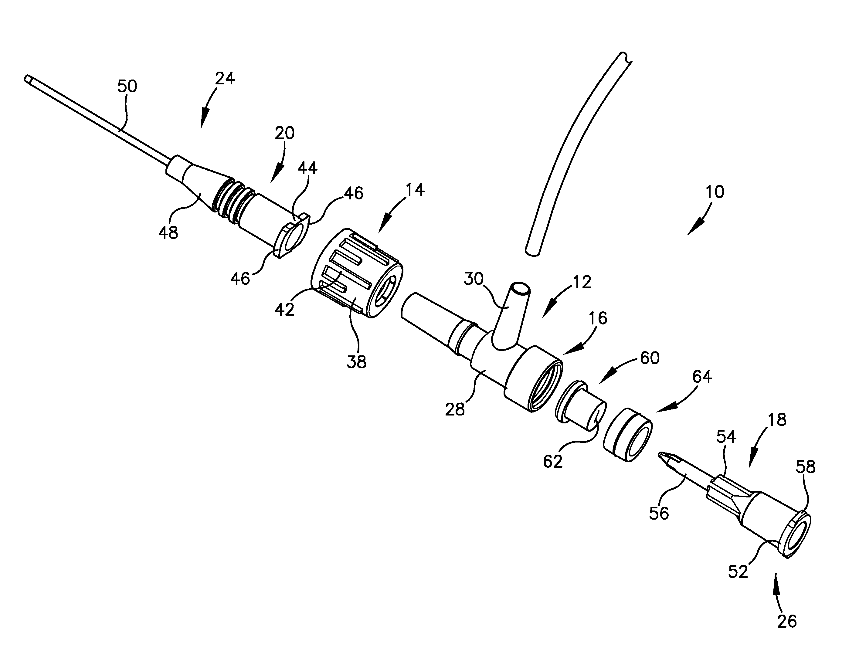
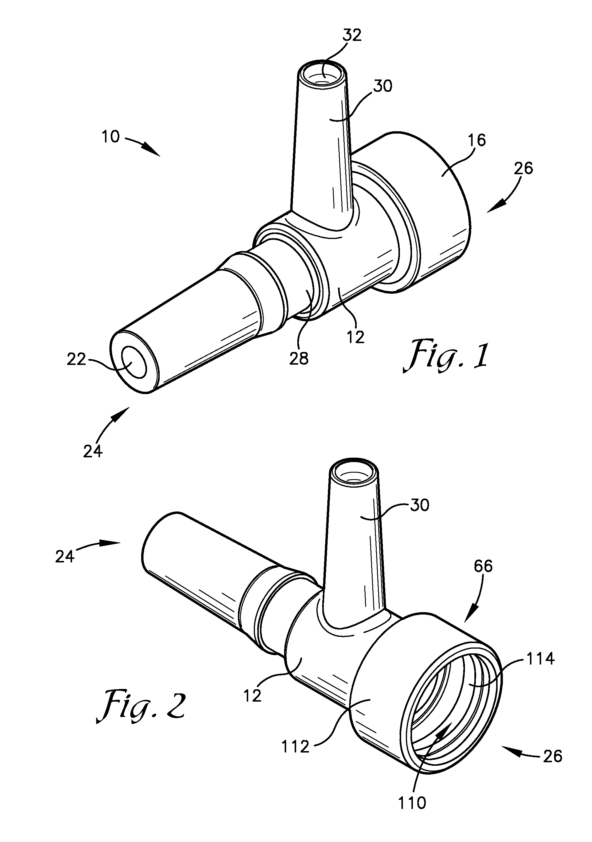
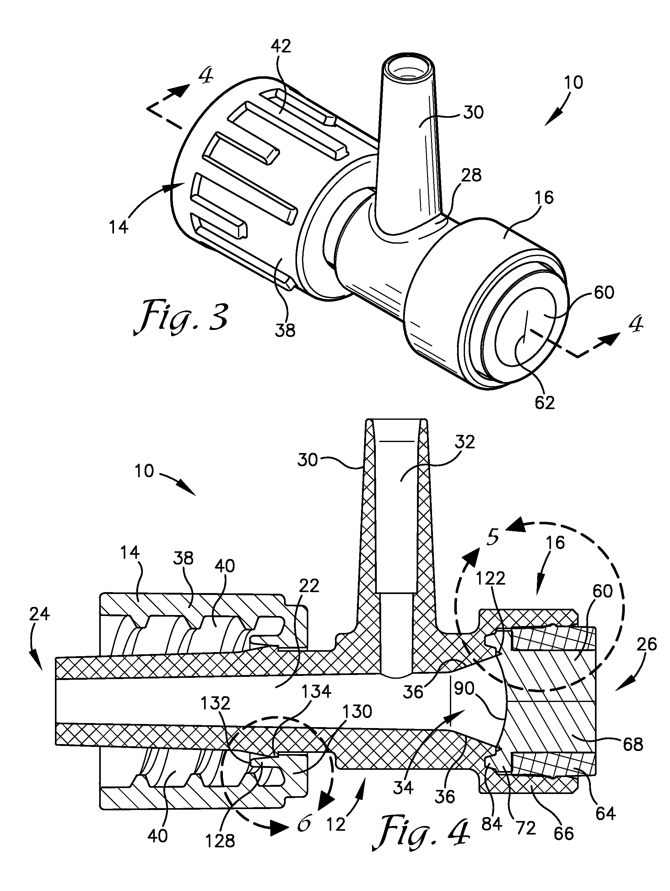
An intravenous injection site having a split septum assembly interfit with the site for the intravenous administration of fluids to a patient. The split septum assembly has a resilient and compressible split septum having an axially-formed slit for receipt of a blunt cannula, needle, or other medical device through said slit, a septum holder for receipt of the split septum, and a septum housing for receipt of the combined septum holder and split septum. The septum includes a body and a flange extending radially from the body. A projection extends from the flange. The septum is mounted within the septum holder, and the septum holder is mounted within the septum housing to provide axial compression of the flange. This axial compression presents a double hermetic seal that significantly minimizes or prevents proximal leakage of fluid through the slit or around the septum holder when the cannula is removed.

Description

RELATED APPLICATION[0001]The present non-provisional application claims priority benefit, with regard to all common subject matter, of U.S. Provisional Application No. 61 / 937,804, filed Feb. 10, 2014, and entitled “SPLIT SEPTUM ASSEMBLY FOR AN INTRAVENOUS INJECTION SITE” (the '804 Provisional Application). The '804 Provisional Application is hereby incorporated by reference in its entirety.BACKGROUND[0002]1. Field[0003]Embodiments of the invention relate to intravenous injection sites for the administration of fluids to a patient. More particularly, embodiments are directed to an intravenous injection site having a split septum assembly in fluid communication and interfit with the site.[0004]2. Related Art[0005]Intravenous devices are used to administer medicaments and other parenteral fluids to patients. The devices include an injection site having a fluid passageway. A distal end of the casing near the patient is coupled with a catheter, needle, or other medical device inserted in...

Claims


Application Information

Patent Timeline
Patent Type & Authority Applications(United States)
IPC IPC(8): A61M39/04
CPCA61M2039/0205A61M39/045A61M2039/0063A61M2039/0072
Inventor WINSOR, CHRIS
Owner NEXUS MEDICAL LLC
Learn More