Torque multiplier for a vehicle transmission flange nut

a technology of transmission flange nut and torque multiplier, which is applied in the direction of wrenches, screwdrivers, manufacturing tools, etc., can solve the problem that the torque multiplier is not suitable for applying the required torque to the six-speed transmission flange nu

Inactive Publication Date: 2015-07-23
HONDA MOTOR CO LTD
View PDF4 Cites 4 Cited by
  • Summary
  • Abstract
  • Description
  • Claims
  • Application Information

AI Technical Summary

Problems solved by technology

To this end, torque multipliers are well-known; however, these known torque multipliers are not suitable for applying the required torque to the six-speed transmission flange nut.

Method used


Image

  • Torque multiplier for a vehicle transmission flange nut
  • Torque multiplier for a vehicle transmission flange nut
  • Torque multiplier for a vehicle transmission flange nut

Examples


Embodiment Construction

[0011]It should, of course, be understood that the description and drawings herein are merely illustrative and that various modifications and changes can be made in the structures disclosed without departing from the present disclosure. In general, the figures of the exemplary torque multiplier for a transmission flange nut are not to scale. It will also be appreciated that the various identified components of the exemplary torque multiplier for a transmission flange nut disclosed herein are merely terms of art that may vary from one manufacturer to another and should not be deemed to limit the present disclosure.

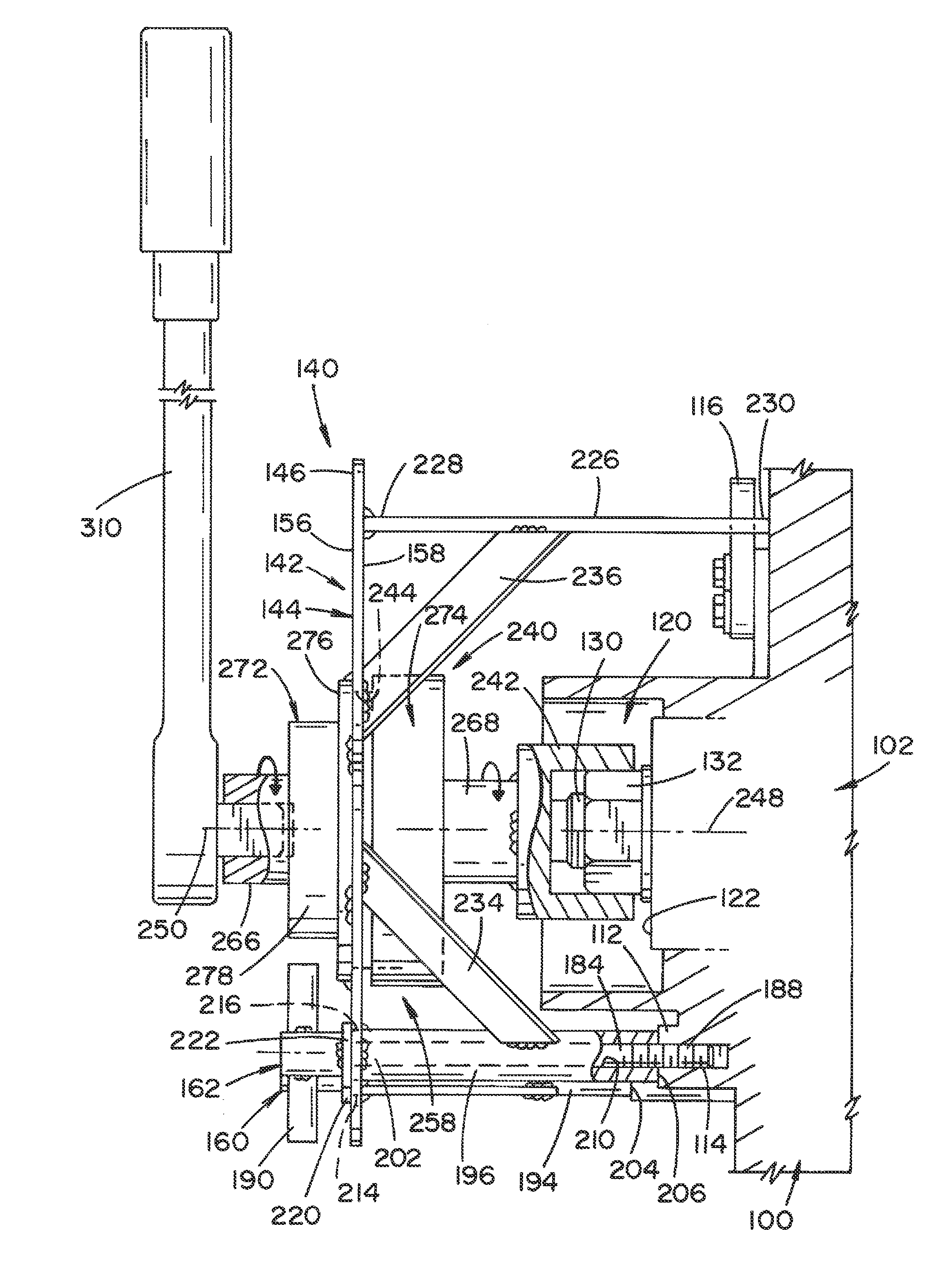
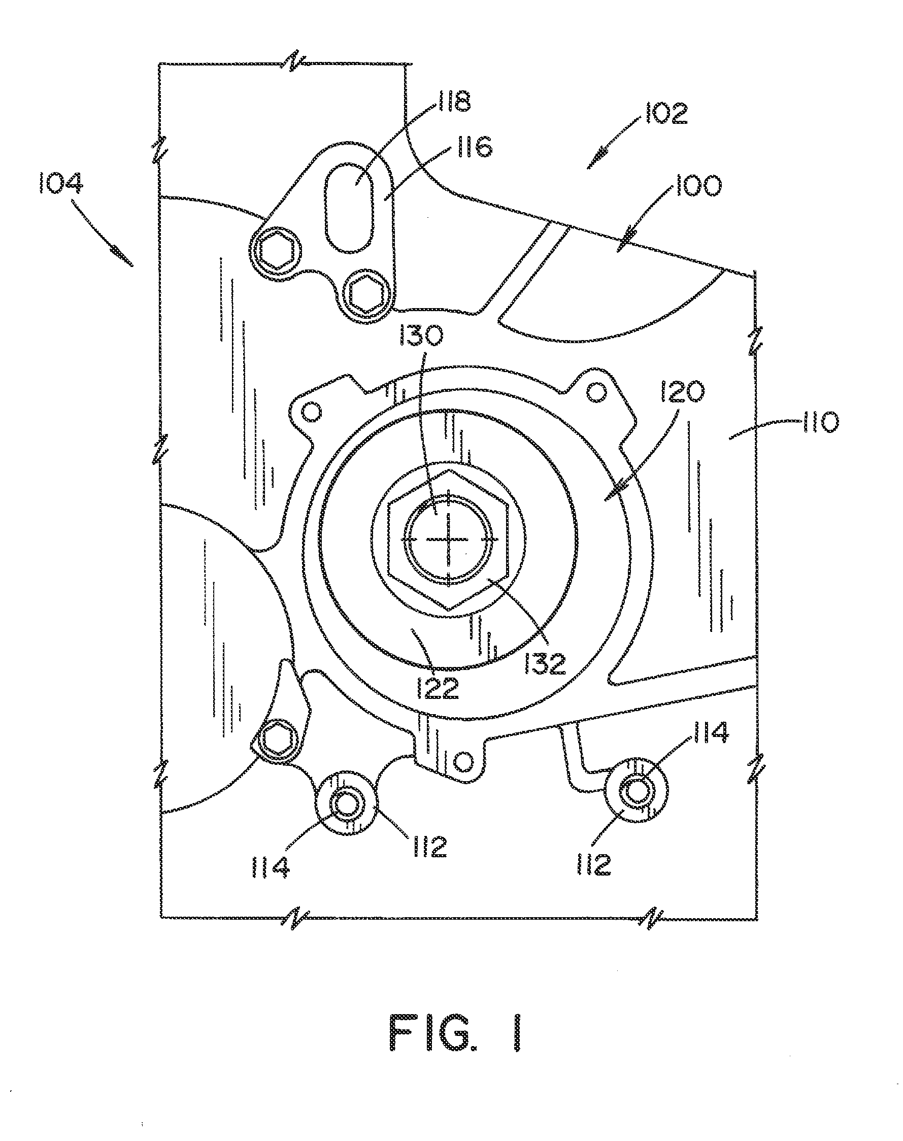
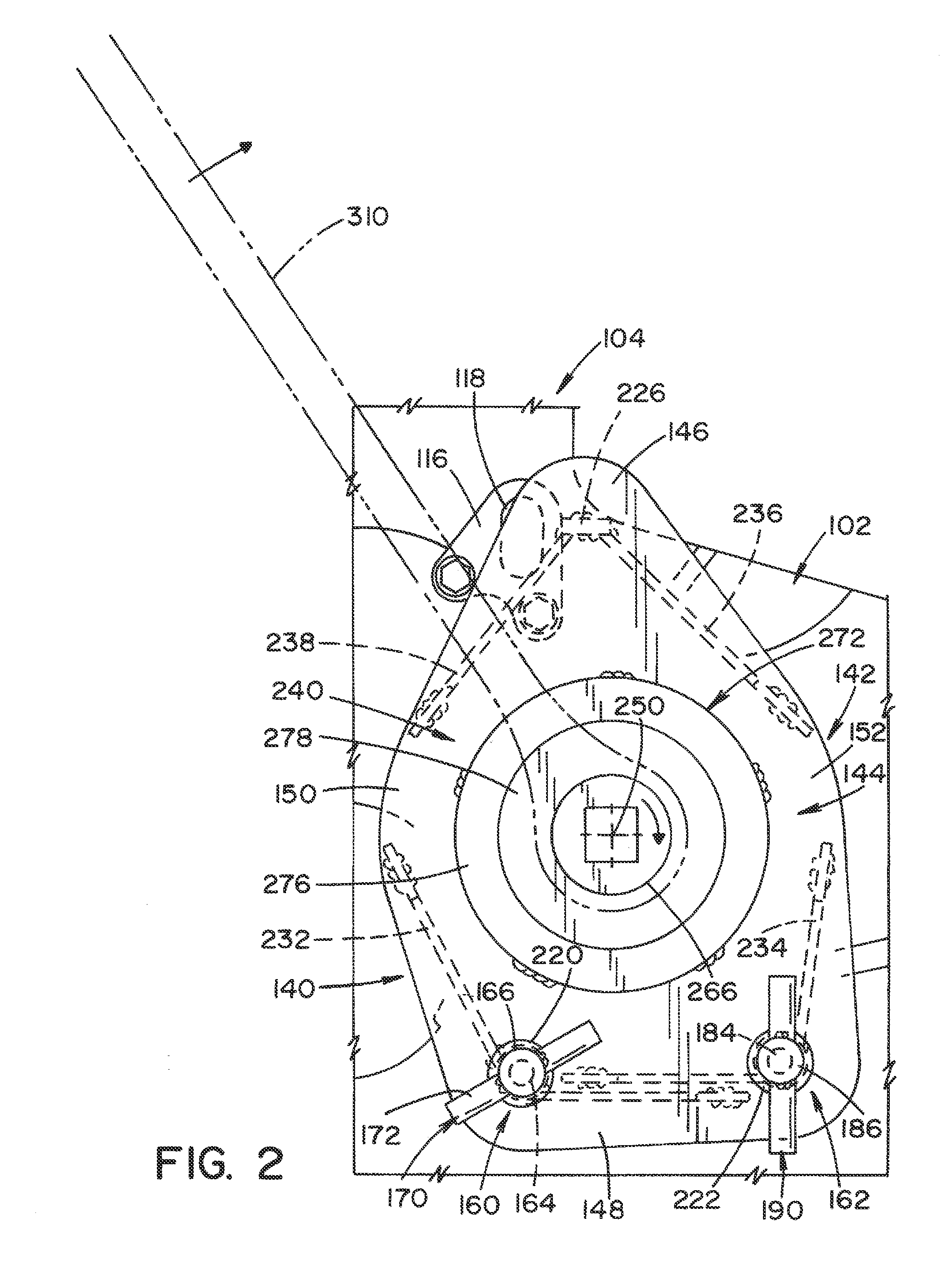
[0012]Referring now to the drawings, wherein like numerals refer to like parts throughout the several views, FIG. 1 schematically illustrates a portion 100 of a case or housing 102 of a transmission 104 of a vehicle engine (not shown). As is well known, a vehicle transmission typically delivers mechanical power from the engine to the remainder of a drive system, such as fix...


PUM


Abstract

A torque multiplier for applying a predetermined torque to a transmission flange nut of a vehicle engine includes a support member for mounting the torque multiplier directly to a transmission case of a vehicle engine. A gear train is secured to the body. A socket is operably connected to the gear train. The socket engages a transmission flange nut.

Description

BACKGROUND[0001]With the advent of six-speed transmissions for vehicle engines, a transmission flange nut having higher torque requirements was required. This flange nut generally requires about 31.5 kgf·m of torque to properly load, for example, transmission bearings, whereas previous flange nuts for five-speed transmissions only required about 18 kgf·m of torque. Therefore, with the increased torque requirements for the flange nut of the six-speed transmission, there is a need to decrease the required applied torque to a level which approximates the required applied torque for the flange nut of the five-speed transmission. To this end, torque multipliers are well-known; however, these known torque multipliers are not suitable for applying the required torque to the six-speed transmission flange nut.BRIEF DESCRIPTION[0002]In accordance with one aspect, a torque multiplier for applying a predetermined torque to a transmission flange nut of a vehicle engine comprises a support member...

Claims


Application Information

Patent Timeline
Patent Type & Authority Applications(United States)
IPC IPC(8): B25B17/02B25B27/00B25B23/00
CPCB25B17/02B25B27/0035B25B23/0007B25B23/0078
Inventor SANDERS, ZACHARYGOWENS, JOSHUAROBINSON, JASON H.HAMMIT, ANDREW L.CARPENTER, JERRY L.BOGAN, ETOBIA
Owner HONDA MOTOR CO LTD
Why Eureka
Try Eureka