
Retractor tools for minimally invasive hip surgery

a technology of retraction tools and hip replacement, which is applied in the field of minimally invasive hip replacement surgery, can solve the problems of limiting mobility and the ability to perform daily living activities, necrosis of the tissue that borders the incision, and requiring a longer recovery period and rehabilitation time for patients, so as to reduce tissue necrosis, minimize visual obstruction, and improve the line of site

Active Publication Date: 2015-07-16
WILSON GREATBATCH LTD
View PDF10 Cites 3 Cited by
  • Summary
  • Abstract
  • Description
  • Claims
  • Application Information

AI Technical Summary

Benefits of technology

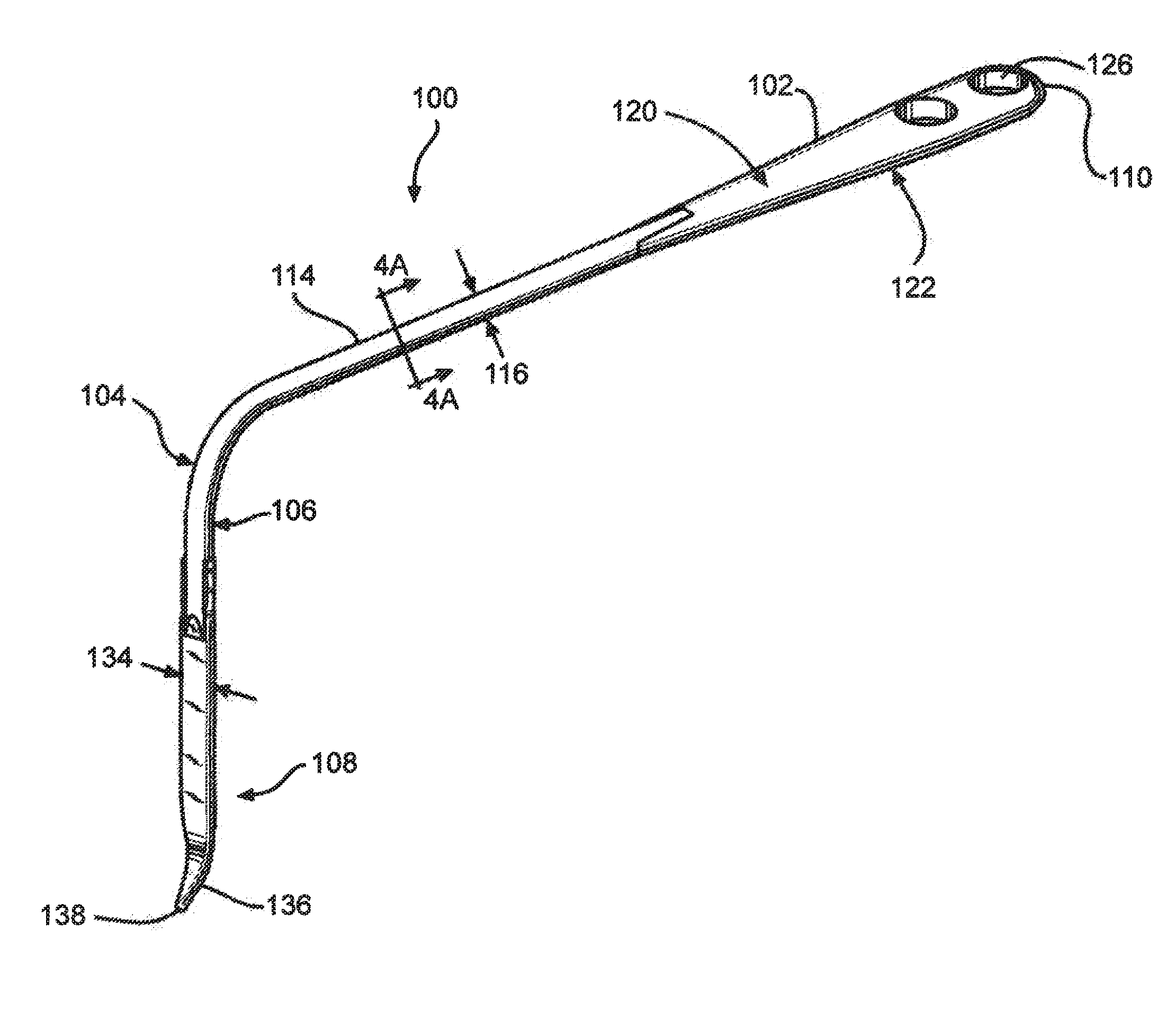
The patent describes a retractor used in hip replacement surgery that has a curved shape to prevent damage to the patient's tissue during the procedure. The retractor has a handle and a curved bend that contacts the patient's wound and the bone marrow. The curved shape of the shaft also improves visibility during the surgery and allows for better control of the tool. Overall, this design reduces tissue damage and improves the efficiency of the surgery.

Problems solved by technology

The usual reasons for hip replacement are osteoarthritis, rheumatoid arthritis and traumatic arthritis, all of which can cause pain and stiffness that limit mobility and the ability to perform daily living activities.
However, such procedures require a longer recovery period and rehabilitation time for the patient.
However, the use of conventional retractors in MIS hip surgery has often resulted in necrosis of the tissue that borders the incision and against which the retractors are pressed to maintain the access path to the surgical site.
This frequently results in impingement on the rotating reamer as the latter is inserted through the incision to ream the acetabulum.

Method used


Image

  • Retractor tools for minimally invasive hip surgery
  • Retractor tools for minimally invasive hip surgery
  • Retractor tools for minimally invasive hip surgery

Examples


Embodiment Construction

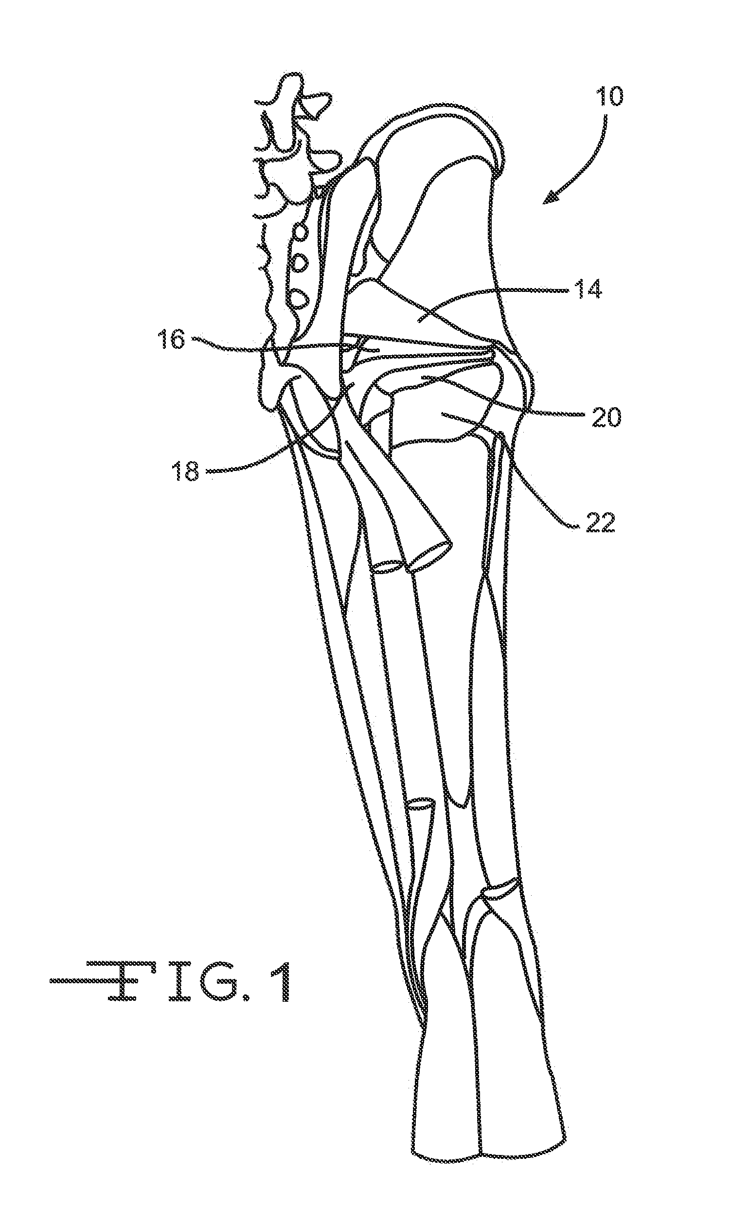
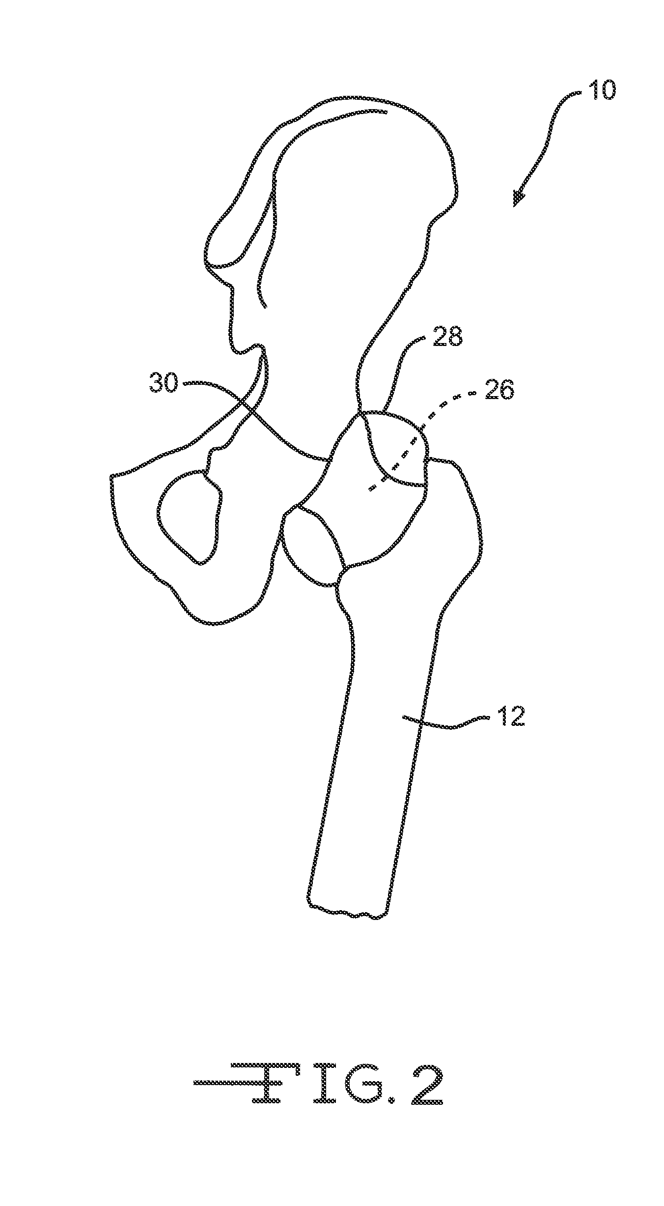
[0036]Now turning to the figures, FIGS. 1-3 illustrate some features of the musculoskeletal anatomy, specifically the hip region 10 of a human. FIGS. 4-18 illustrate embodiments of orthopedic retractor tools of the present invention. As shown in FIGS. 1-3, there are several muscles that act to stabilize the femoral head of a femur bone 12 in the acetabulum (FIG. 2). These muscles include the short external rotator muscles (i.e., the piriformis 14, the superior gemellus 16, the obturator internus 18, the inferior gemellus 20, the obturator externus (not shown) and the quadratus femoris 22). The gluteus maximus (not shown) extends over these short external rotator muscles. The femoral head 26 is enclosed in a fibrous capsule 28, which attaches to the hip bone outside the acetabular lip 30 and to the base of the neck of the femoral head 26.

[0037]The MIS posterior hip replacement approach has traditionally involved first a skin incision, followed by an incision in the fascia lata, and t...


PUM


Abstract

A retractor system, kit and method of use includes a plurality of retractors for use in retracting a wound during a minimally-invasive hip replacement surgery to define an access space to a surgical site is discussed. Each of the retractors comprises a handle portion configured to be held by a user, a curved bend portion distal of the handle portion, and a wound contact portion attached to the curved bend portion. The wound contact portion is configured to contact tissue of the wound when at least a portion of the retractor is inserted through a skin incision that defines the wound. Each retractor also has a distal portion disposed distally of the wound contact portion, wherein the wound contact portion has a generally curved cross-sectional profile perpendicular to its length that is configured to prevent necrosis of the tissue during retraction. In addition, the cross-sectional profile provides an improved line of sight during the surgical procedure. Furthermore, the cross-sectional profile prevents the jamming of a cutting device, such as a reamer inserted through the incision, while the retractors retract the wound.

Description

CROSS-REFERENCE TO RELATED APPLICATIONS[0001]This application is a continuation of U.S. patent application Ser. No. 13 / 194,176, filed on Jul. 29, 2011, now abandoned, which claims priority from U.S. Pro. Pat. App. Ser. Nos. 61 / 368,754, filed Jul. 29, 2010; 61 / 368,761, filed Jul. 29, 2010; and 61 / 368,768 filed Jul. 29, 2010.1. FIELD OF THE INVENTION[0002]The present invention is directed to minimally invasive surgery, and more particularly to retractor tools for use in minimally invasive hip replacement surgery.2. PRIOR ART[0003]Approximately 200,000 hip replacements are performed each year in the United States and the number is expected to continue to grow as the population continues to age. The usual reasons for hip replacement are osteoarthritis, rheumatoid arthritis and traumatic arthritis, all of which can cause pain and stiffness that limit mobility and the ability to perform daily living activities. Hip replacement surgery is usually performed where other measures (e.g. physic...

Claims


Application Information

Patent Timeline
Patent Type & Authority Applications(United States)
IPC IPC(8): A61B17/02
CPCA61B17/0218A61B2017/0088A61B2017/0275A61B17/025
Inventor RYSHKUS, CHAD E.ROGER, DOUGLAS J.CRANDALL, JONATHAN P.
Owner WILSON GREATBATCH LTD
Learn More