Mantel With Hidden Mounting Assembly

a technology of mounting assembly and mantel, which is applied in the field of mantel or shelf, can solve the problems of not always the same distance between adjacent vertical wall studs in a wall, other articles are relatively bulky or heavy in weight, and the type of securement is generally considered less desirable for weight baring reasons than securing directly to a stud

Active Publication Date: 2015-07-02
NIES JOEL M
View PDF29 Cites 6 Cited by
  • Summary
  • Abstract
  • Description
  • Claims
  • Application Information

AI Technical Summary

Benefits of technology

The present invention is a mantel and hidden mounting assembly that has several technical advantages. First, it is strong and secure to the wall, with a sheet metal bracket that supports the weight of the object placed on it. The bracket allows for a strong connection to the wall while distributing the torque loads evenly. Second, the design is user-friendly, with a linear mounting bracket that can be easily aligned and secured to the wall. The bracket allows for easy adjustment of the position of the mantel or shelf on the wall. Third, it is flush with the wall, with a unique L-shaped mounting bracket that allows for a seamless engagement with the wall. Fourth, it is adaptable to different mounting locations, with the ability to shift the bracket and fasteners to a different wall stud. Fifth, it is efficient to manufacture and cost-effective, with reclaimed wood being a common material. The mounting slot and recess are easily cut, and the bracket is formed from inexpensive materials. Overall, the invention provides a strong, secure, and user-friendly mounting solution for various decorative purposes.

Problems solved by technology

Other articles are relatively bulky or heavy in weight, such as detergent containers, boxes of soda, television sets and the like.
One problem with conventional hidden shelving mounting hardware designs is that the predrilled rod receiving holes in the thinner shelving boards are spaced apart fixed distance, presumably to retain the weight supporting integrity of the thinner boards.
Yet, the distance between adjacent vertical wall studs in a wall are not always the same.
While the use of wall anchors can be used when a wall stud is not present, this type of securement is generally considered less desirable for weight baring reasons than securing directly to a stud.
Another problem with conventional hidden shelving mounting hardware is that it is designed for thinner shelving boards.
A further problem with conventional hidden shelving mounting hardware designs is that they are intended for shelving boards made of a uniform and consistent composite material.
The designs are not intended or well suited for use with reclaimed wood that is frequently cracked or split, or includes knots, embedded nails or other discontinuities or imperfections.
The French cleat suffers from a variety of problems for mounting a solid wood mantel, particularly one made of reclaimed wood.
By their nature and for aesthetic reasons, reclaimed wood mantels have cracks, splits, knots and other discontinuities.
Any discontinuities in the vicinity of the routed groove can prevent proper alignment of the cleats, or weaken the mounting joint or cause it to fail.
Forming the cleat groove requires additional manufacturing costs, such as the cost of an industrial router to cut through the hardened reclaimed wood, and frequent replacement of expensive routing tool blades due to the nails and other objects in the wood.
Furthermore, consumers frequently have no special carpentry skills or training to install the mantel, and thus frequently secure the wall cleats slightly misaligned so they do not properly align with the routed groove in the back of the mantel.
This causes unsightly gaps between the mantel and the wall, or shifting or jiggling of the mantel when it is bumped or items are placed on it.

Method used


Image

  • Mantel With Hidden Mounting Assembly
  • Mantel With Hidden Mounting Assembly
  • Mantel With Hidden Mounting Assembly

Examples


Embodiment Construction

[0036]While this invention is susceptible of embodiment in many different forms, the drawings show and the specification describes in detail preferred embodiments of the invention. It should be understood that the drawings and specification are to be considered an exemplification of the principles of the invention. They are not intended to limit the broad aspects of the invention to the embodiments illustrated.

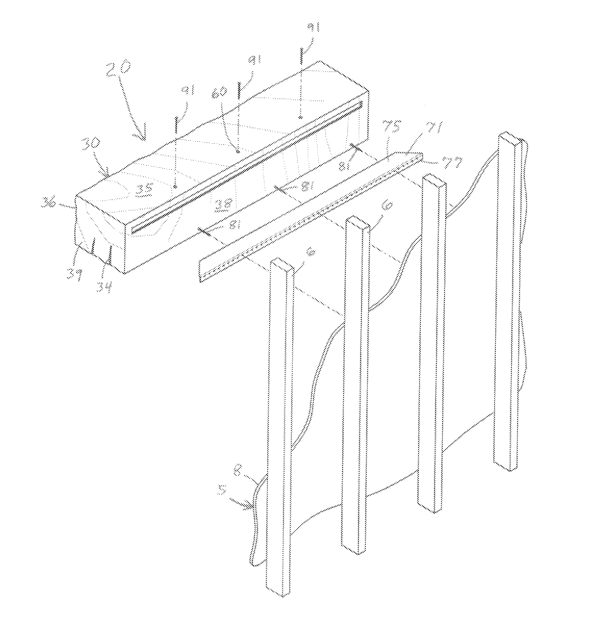
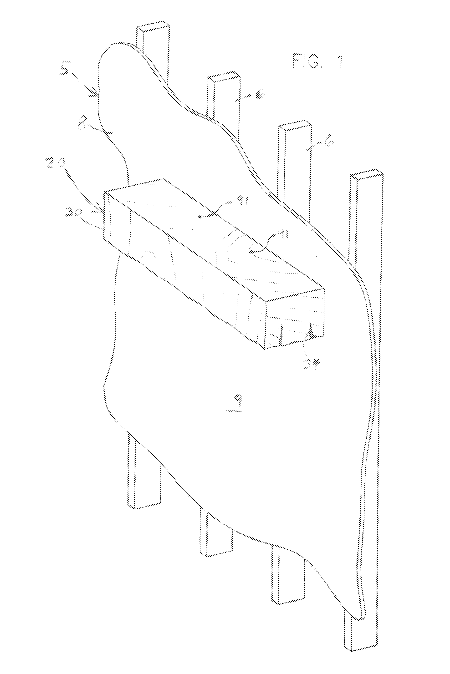
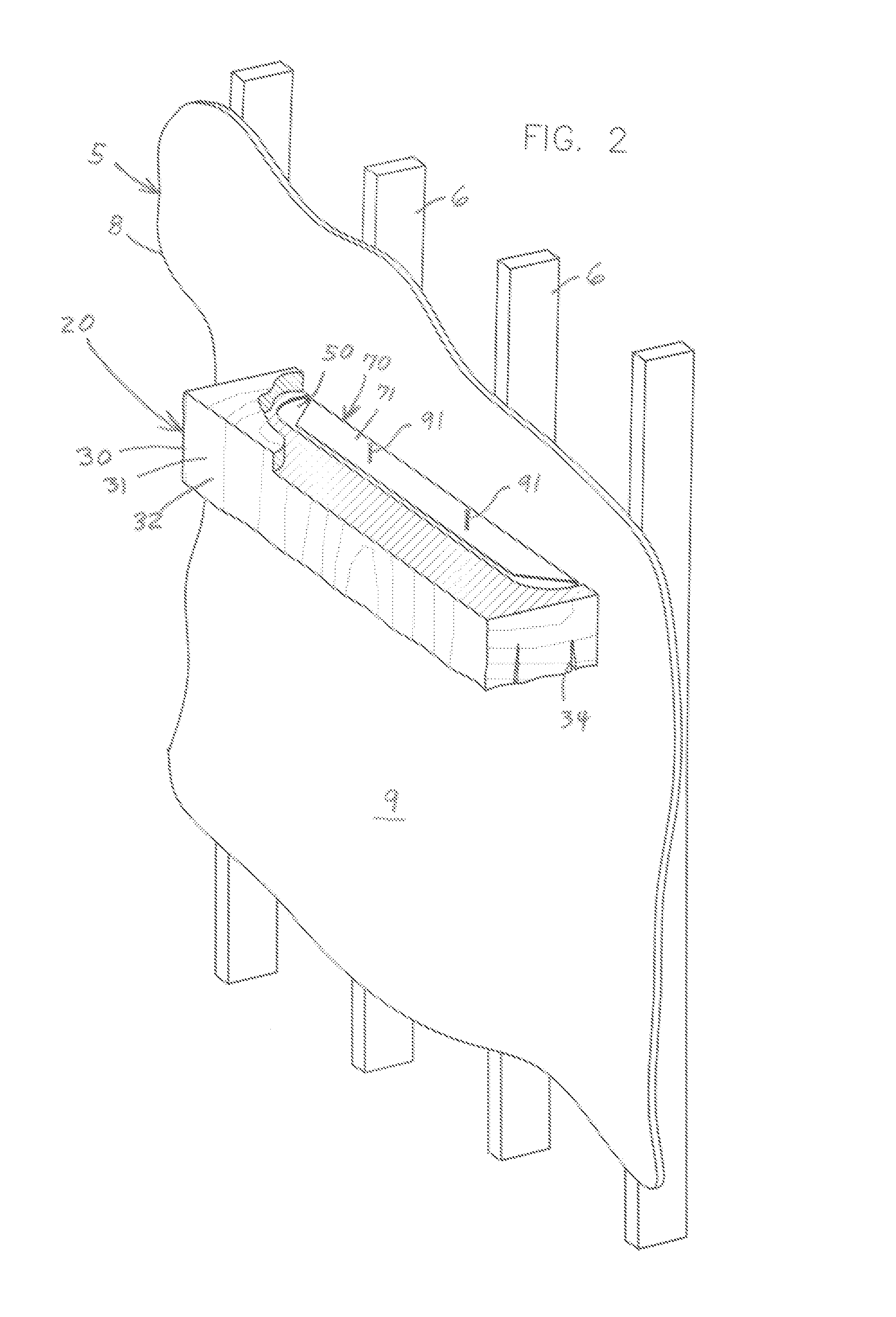
[0037]Building walls 5 commonly include a wall frame with uniformly spaced vertical wall studs 6. The wall studs 6 are typically spaced apart about 16 inches. Drywall or another suitable wall forming material 8 is placed over and secured to the wall frame and its studs 6. The outer surfaces 9 of the drywall 8 form the visible surfaces of a room. The wall frame and studs 6 are internal and remain hidden from view. Shelving and mantels are used to elevate items off the floor and display or support them on the vertical wall 5. Shelves and mantels project out from the outer surfac...


PUM


Abstract

The invention is a mantel or shelf made of a solid block of reclaimed wood with a hidden mounting assembly. The mantel has sufficient thickness, depth and length to accommodate an elongated L-shaped sheet metal bracket with planar horizontal and vertical flanges to allow selective lateral positioning of the mantel relative to its securement to spaced vertical wall studs. An L-shaped opening in the rear of the mantel is formed by a deep horizontal slot and a shallow vertical recess extending down from the slot. The slot is parallel to and near the top of the mantel, and receives the horizontal flange. The recess receives the vertical flange so the mantel is flush with the wall. A mounting fastener inserted into the mantel pierces the horizontal flange to capture the bracket and secure the mantel to the wall. The bracket, slot and recess are hidden from view during use.

Description

TECHNICAL FIELD OF THE INVENTION[0001]This invention pertains to a mantel or shelf made of a solid block of reclaimed wood of sufficient thickness, depth and length to receive, hide and work with its mounting hardware to support objects, where the hardware includes an elongated bracket with a vertical flange secured to the wall studs, and a horizontal flange received by an elongated slot in the mantel, and with a mounting fastener to pierce the captured flange to secure the mantel to the bracket and wall.BACKGROUND OF THE INVENTION[0002]Shelving for residential and commercial applications is commonly used to display or store a wide variety of articles to reduce clutter or improve the physical or visible access to the articles. Some articles are relatively compact or light in weight, such as pictures, antiques, family heirlooms, knickknacks and the like. Other articles are relatively bulky or heavy in weight, such as detergent containers, boxes of soda, television sets and the like. ...

Claims


Application Information

Patent Timeline
IPC IPC(8): A47B96/02A47B96/06
CPCA47B96/061A47B57/52E04F19/005A47B96/027A47B96/028A47B96/066A47B57/56
Inventor NIES, JOEL M.
Owner NIES JOEL M
Why Eureka
Try Eureka