
Monitoring system and a monitoring method for a wind turbine generator

a monitoring system and wind turbine technology, applied in the direction of machines/engines, instruments, using mechanical means, etc., can solve the problems of increasing the fluctuating load received by the wind turbine generator, increasing the loss of the operator or the manufacturer, and increasing the time for replacemen

Inactive Publication Date: 2015-06-25
MITSUBISHI HEAVY IND LTD
View PDF4 Cites 28 Cited by
  • Summary
  • Abstract
  • Description
  • Claims
  • Application Information

AI Technical Summary

Benefits of technology

The patent text describes a monitoring system for wind turbines that uses a load measurement device to determine the fatigue load on the wind turbine components. However, this method is expensive and requires frequent maintenance and calibration. To solve this problem, the patent proposes a monitoring system that uses a wind speed obtaining unit, a wind condition identifying unit, and a fatigue load calculating unit. The wind condition identifying unit identifies the wind condition parameter, such as wind shear or upflow angle, based on the wind speed and the power output or pitch angle of the wind turbine. The wind condition parameter is then used to calculate the fatigue load of the wind turbine component using the wind energy and the wind condition parameter. This monitoring system is simpler and more cost-effective than using a load measurement device and can provide reliable monitoring without the need for additional anemometers.

Problems solved by technology

When an actual wind condition is more severe than the design assumption, the fluctuating load received by the wind turbine generator increases.
Thus, there is a possibility for each component of the wind turbine generator (a blade, nacelle, tower or auxiliary machine, for instance) to be damaged before the time expected in design, thus hastening the time for replacement.
In the case where an unexpected damage is caused, there is a concern of occurrence of a downtime for taking time to arrange the parts and work for replacement, which leads to increase in the loss of the operator or the manufacturer.

Method used


Image

  • Monitoring system and a monitoring method for a wind turbine generator
  • Monitoring system and a monitoring method for a wind turbine generator
  • Monitoring system and a monitoring method for a wind turbine generator

Examples


Embodiment Construction

[0047]At least one embodiment of the present invention will now be described in detail with reference to the accompanying drawings. It is intended, however, that unless particularly specified, dimensions, materials, shape, its relative positions and the like shall be interpreted as illustrative only and not limitative of the scope of the present invention.

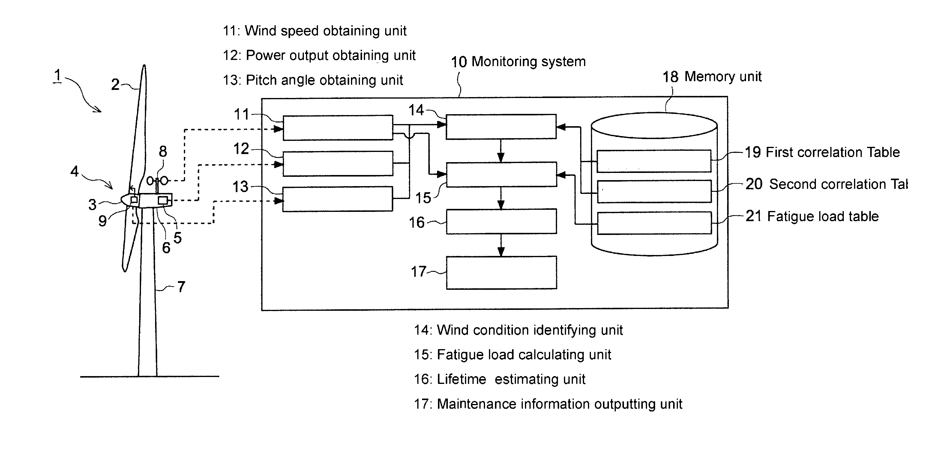
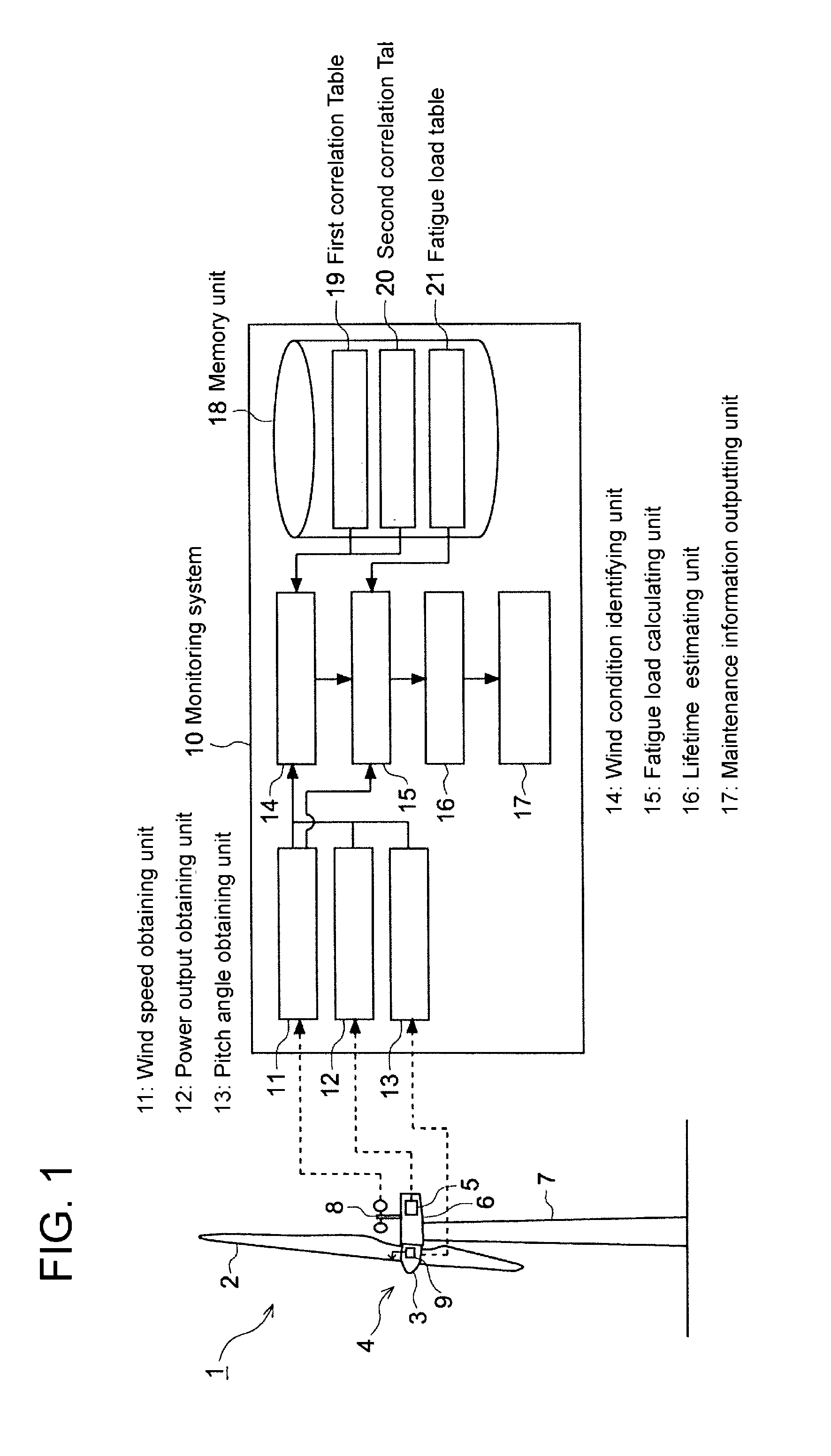
[0048]FIG. 1 is an illustration of a configuration of a wind turbine generator and a monitoring system according to one embodiment.

[0049]In FIG. 1, illustrated is an exemplary configuration of a wind turbine generator 1 to which a monitoring system 10 according to the embodiment is applied. The wind turbine generator 1 includes a rotor 4 which has at least one blade 2 and a hub 3, and a generator 5 which is configured to be driven by rotation energy of the rotor 4, a nacelle 6 which rotatably supports the rotor 4, and a tower 7 to which the nacelle 6 is attached. The wind turbine generator 1 may be provided either on the ground or ...


PUM


Abstract

A monitoring system for a wind turbine generator comprises: a wind speed obtaining unit for obtaining a wind speed; a wind condition identifying unit for identifying a wind condition parameter which includes at least one of a wind shear or an upflow angle of a wind which acts on a rotor of the wind turbine generator based on the wind speed obtained by the wind speed obtaining unit and at least one of a power output or a pitch angle of the wind turbine generator measured upon occurrence of the wind speed; and a fatigue load calculating unit for calculating a fatigue load of a component of the wind turbine generator based on at least the wind condition parameter identified by the wind condition identifying unit and a wind turbulence intensity of the wind which acts on the rotor.

Description

TECHNICAL FIELD[0001]The present disclosure relates to a monitoring system and a monitoring method for a wind turbine generator for monitoring a wind turbine generator.BACKGROUND ART[0002]In recent years, from the perspective of preserving the environment, a wind turbine generator which generates electrical power using wind energy has attracted attention. Generally, a wind turbine generator includes a rotor where a plurality of blades is attached to a hub, and a generator which is configured to be driven by rotation energy of the rotor which rotates upon receiving wind.[0003]Wind conditions received by a wind turbine generator normally vary due to the influence of the terrain and the like. When an actual wind condition is more severe than the design assumption, the fluctuating load received by the wind turbine generator increases. Thus, there is a possibility for each component of the wind turbine generator (a blade, nacelle, tower or auxiliary machine, for instance) to be damaged b...

Claims


Application Information

Patent Timeline
IPC IPC(8): F03D11/00G01P5/00G01W1/00G01M15/14
CPCF03D11/0091G01W1/00G01P5/00G01M15/14F03D7/0292F05B2270/32F05B2270/328F05B2270/332F05B2270/335F03D17/00Y02E10/72
Inventor KARIKOMI, KAIMATSUO, TORU
Owner MITSUBISHI HEAVY IND LTD
Learn More