
Dispensing device for welding rod dryer

Active Publication Date: 2015-06-18
DOOSAN HEAVY IND & CONSTR CO LTD
View PDF11 Cites 5 Cited by
  • Summary
  • Abstract
  • Description
  • Claims
  • Application Information

AI Technical Summary

Benefits of technology

The patent describes a dispensing device for a welding rod dryer that can maintain the temperature of the dryer while receiving a welding rod, allowing multiple operators to quickly and easily dispense dryers. The device is designed to smoothly connect the dryers, regardless of their shape, and can be used as a single unit. This invention simplifies the welding process and improves efficiency.

Problems solved by technology

If the cladding material of the welding rod is stripped or the welding rod becomes wet with moisture, the welding rod may not be operational, or the arc cannot be smoothly generated, so that a difficult situation in the use of the welding rod may frequently occur.
Accordingly, in the case of heavy industry fields, delay time is significantly taken until many welding operators select and receive their respective welding rod dryers at a time.
In other words, predetermined time is required to preheat the portable welding rod dryer, and the welding operation must significantly and inconveniently be delayed for the welding rod dryer for time ranging from several tens of minutes to several hours.
Accordingly, not only is too much time wasted, but also manpower of many welding operators is remarkably wasted.
Further, since the welding rod stored in the drying oven must be drawn from the drying oven and received in the portable welding rod dryer again even though the heating of the portable welding rod dryer has been finished, procedures are remarkably complex and inconvenient.

Method used


Image

  • Dispensing device for welding rod dryer
  • Dispensing device for welding rod dryer
  • Dispensing device for welding rod dryer

Examples


Embodiment Construction

[0044]Hereinafter, exemplary embodiments will be described in more detail with reference to accompanying drawings.

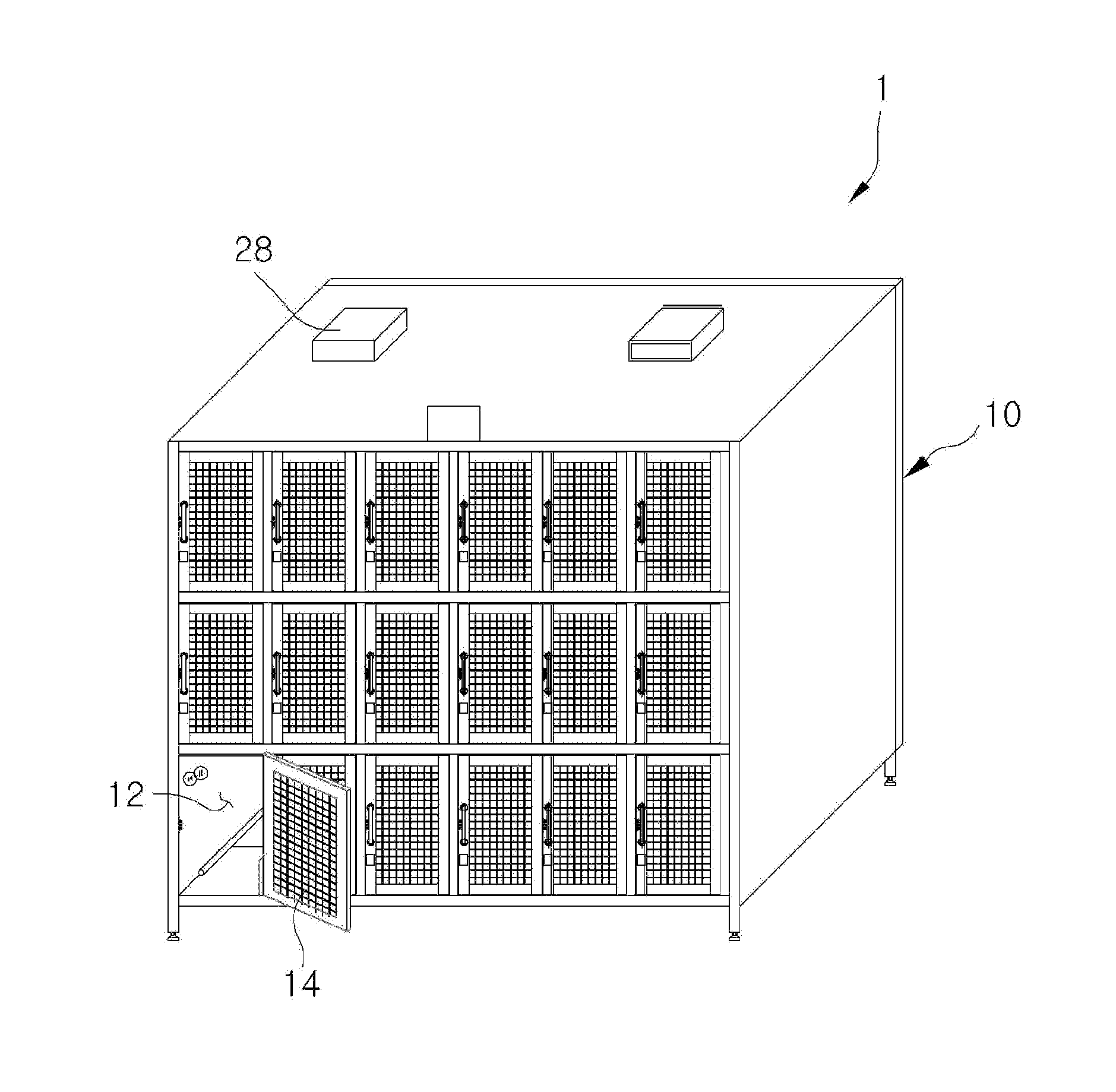
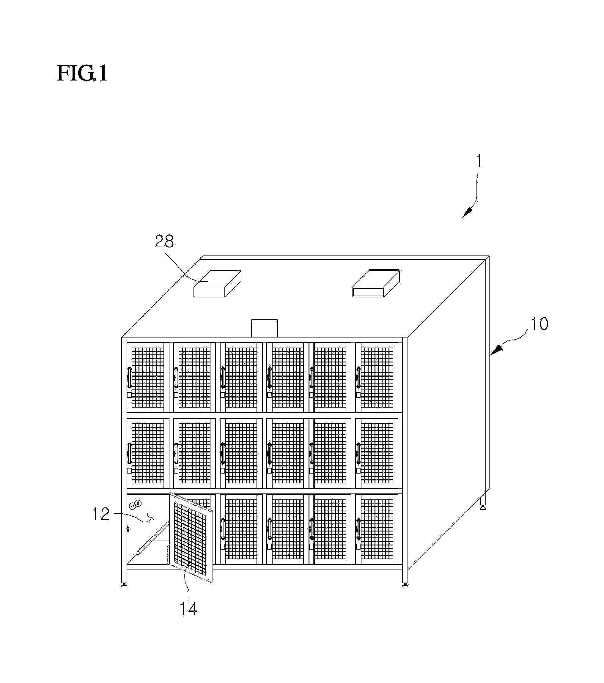
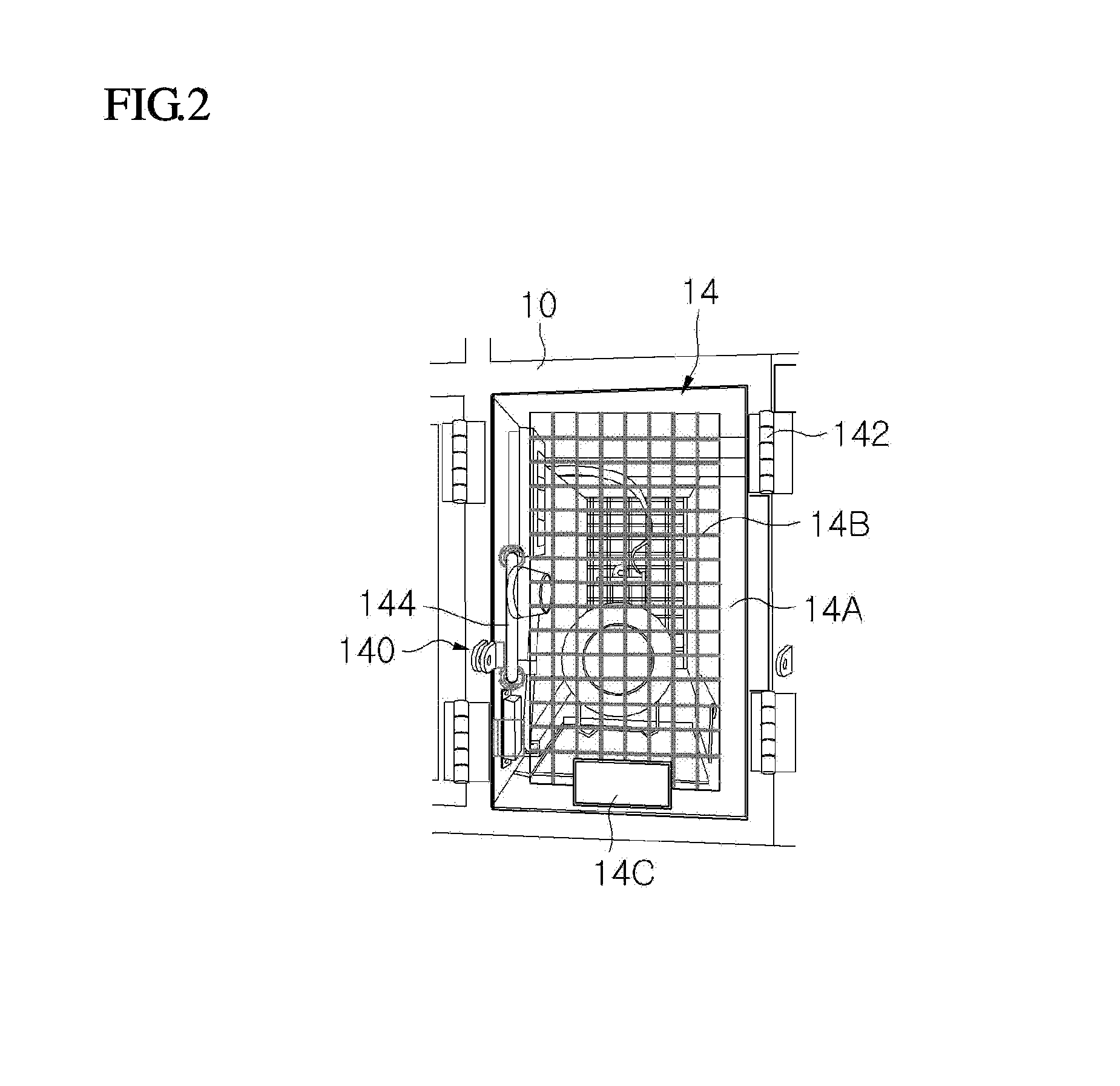
[0045]FIG. 1 is a perspective view showing an entire structure of a dispensing device 1 according to an exemplary embodiment. FIG. 2 is a partially enlarged view showing a chamber 12 having a door 14 in a closed state according to an exemplary embodiment. FIG. 3 is a partially enlarged view showing the chamber 12 having the door 14 in an open state according to an exemplary embodiment.

[0046]As shown in figures, provided is a dispensing device 1 capable of simultaneously dispensing a great number of welding rod dryers D generally known to those skilled in the art, as a device for receiving a welding rod (not shown), and preheating the welding rod for the use of the welding rod to prevent a cladding material of the welding rod from being stripped or wet with moisture.

[0047]According to the exemplary embodiment, the welding rod dryer can be maintained at a predetermined tem...


PUM

PropertyMeasurementUnit
Timeaaaaaaaaaa
Poweraaaaaaaaaa

Abstract

There is provided a dispensing device for a welding rod dryer. The dispensing device may include a plurality of chambers configured to receive welding rod dryers; and a connection member provided in each of the plurality of chambers and configured to supply power to the welding dryers; and a door provided at an entrance of each of the plurality of chambers.

Description

CROSS-REFERENCE TO RELATED APPLICATION[0001]This application claims priority to Korean Patent Application No. 10-2013-0158535, filed on Dec. 18, 2013 the disclosure of which is incorporated herein by reference in its entirety.BACKGROUND[0002]1. Field[0003]Apparatuses consistent with exemplary embodiments relate to a dispensing device for a welding rod dryer, and more particularly, to a dispensing device for a welding rod dryer, in which the welding rod dryer can be maintained at a predetermined temperature in the state that the welding rod dryer receives a welding rod without being stored separately from the welding rod, and many welding operators can rapidly dispense welding rod dryers at a time without difficulty and inconveniences.[0004]2. Description of the Related Art[0005]Shielded metal arc welding (SMAW) is a technology first developed among arc welding technologies, and one of the technologies that have been most extensively used until now.[0006]According to the SMAW, an arc...

Claims


Application Information

Patent Timeline
IPC IPC(8): F26B9/06
CPCF26B9/06B23K9/32B23K9/26B25H3/006F26B9/003F26B2210/00B23K9/133B65D85/26F26B23/04
Inventor KONG, HYUN SANGOH, EUN JONG
Owner DOOSAN HEAVY IND & CONSTR CO LTD
Learn More