
Sleeve-Wrap Compression System and Method

a compression system and wrap technology, applied in the field of wrap compression system and method, can solve the problems of time-consuming application process, difficulty in applying multiple layers of wrap, and difficulty in obtaining desired pressure and/or relatively uniform pressur

Inactive Publication Date: 2015-06-11
CAROLON
View PDF6 Cites 14 Cited by
  • Summary
  • Abstract
  • Description
  • Claims
  • Application Information

AI Technical Summary

Benefits of technology

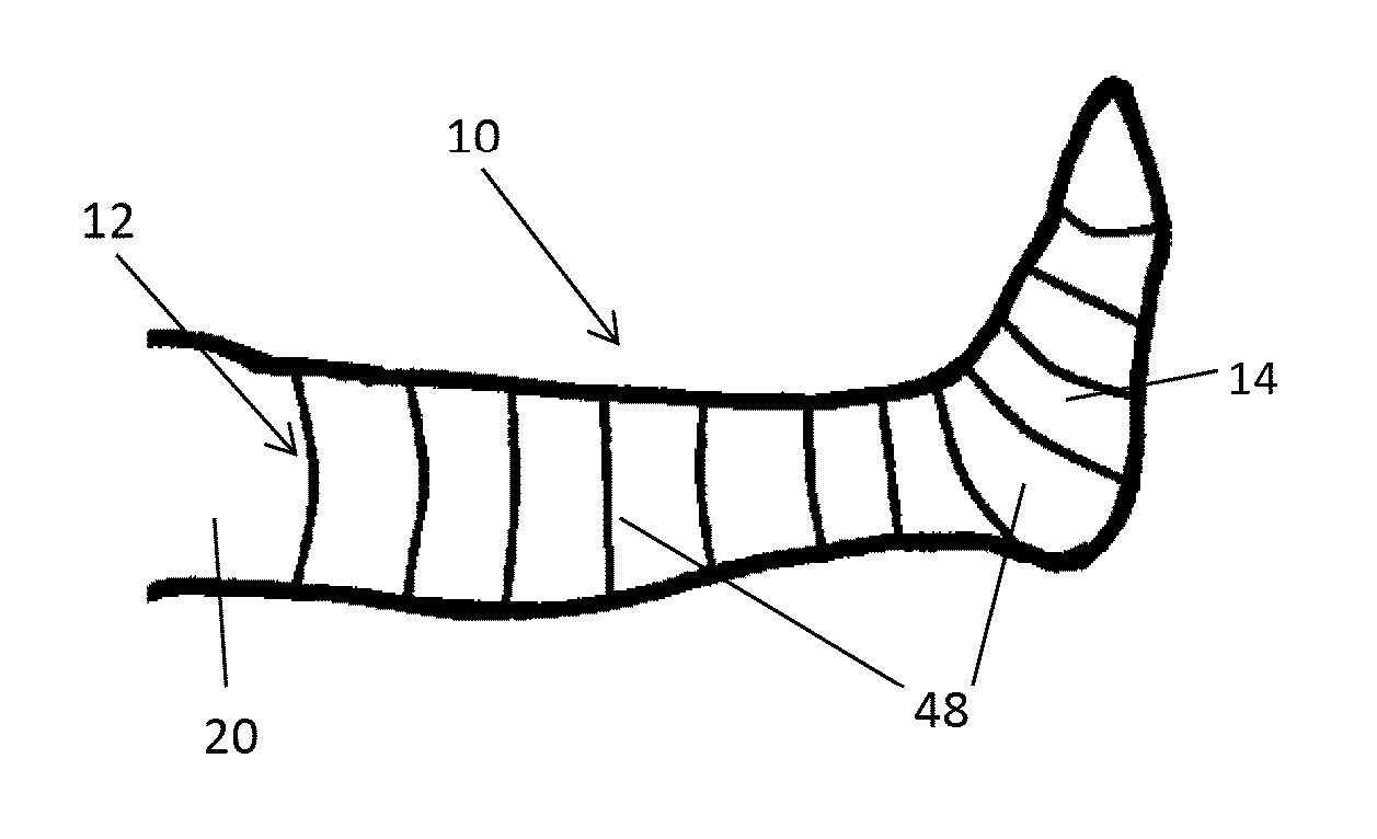
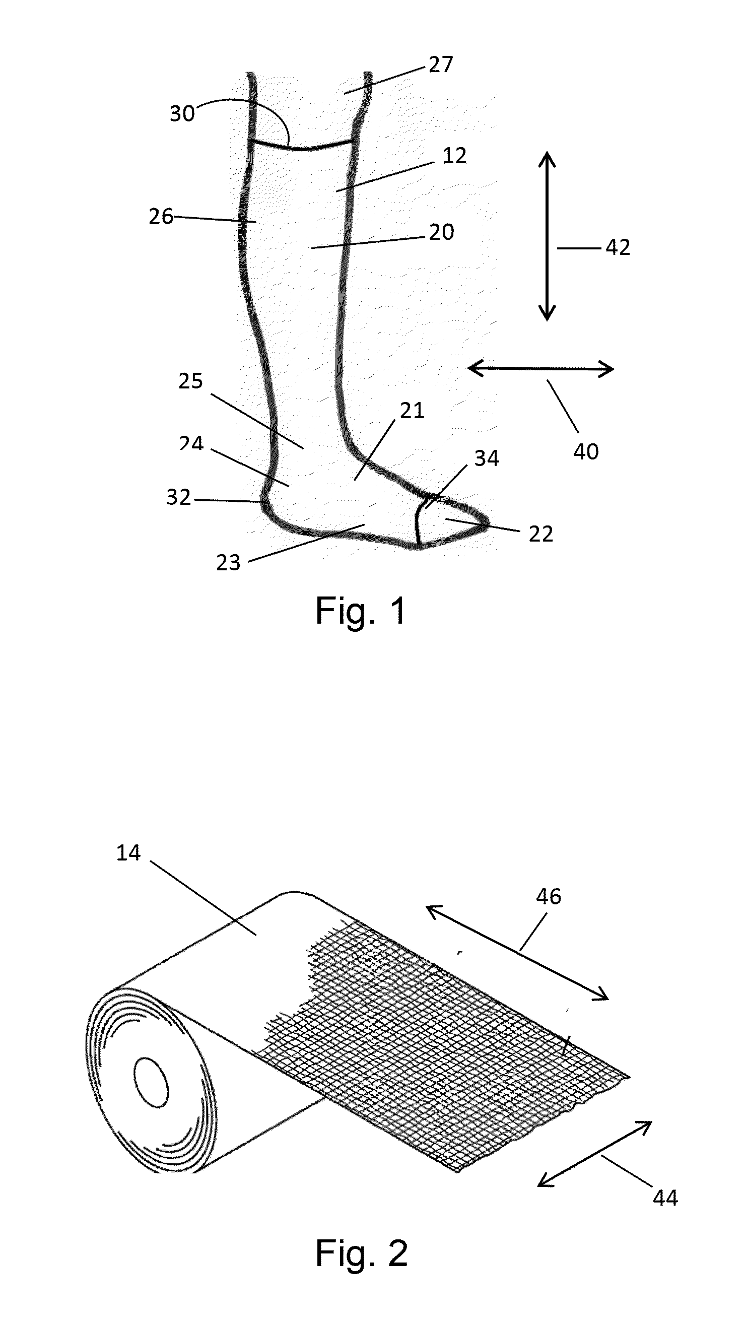
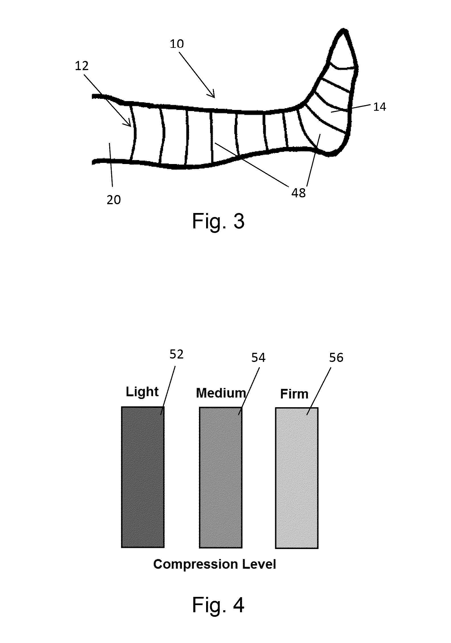
The present invention is a compression system that can be used to treat limbs. The system includes an inner sleeve and an outer wrap, both made of long-stretch elastomeric material. When applied to a patient's limb, the inner sleeve exerts a compressive pressure of about 5-10 mm Hg and the outer wrap exerts a second compressive pressure that frictionally engages the inner sleeve, securing the compression system as a single entity in the therapeutic position on the limb. The inner sleeve is designed to disperse the compressive pressure smoothly about the limb and reduce wrinkling and bunching. The compression system also includes an elastic stress / strain curve that provides a gradual change in the working compression profile in response to changes in limb volume. Additionally, the system can include a color / compression change indication system that allows users to determine the proper amount of stretch for achieving the desired compressive pressure.

Problems solved by technology

Such bandages have disadvantages, including difficulty in applying the multiple layers of bandages, and in particular, to obtain a desired pressure and / or a relatively uniform pressure.
The application process is time consuming.
And, such bandages are prone to slipping and / or forming wrinkles after being applied, which may result in insufficient and / or uneven compression being applied, discomfort to the patient, and / or skin lesions.
However, such systems often do not provide or maintain a desired therapeutic compressive pressure for extended periods of time.
Furthermore, such systems typically still have a tendency to slip and / or wrinkle after application.

Method used


Image

  • Sleeve-Wrap Compression System and Method
  • Sleeve-Wrap Compression System and Method
  • Sleeve-Wrap Compression System and Method

Examples


Embodiment Construction

[0027]For the purposes of this description, unless otherwise indicated, all numbers expressing quantities, conditions, and so forth used in the description are to be understood as being modified in all instances by the term “about.” Accordingly, unless indicated to the contrary, the numerical parameters set forth in the following description are approximations that can vary depending upon the desired properties sought to be obtained by the embodiments described herein. At the very least, and not as an attempt to limit the application of the doctrine of equivalents to the scope of the invention, each numerical parameter should at least be construed in light of the number of reported significant digits and by applying ordinary rounding techniques.

[0028]Notwithstanding that the numerical ranges and parameters setting forth the broad scope of the described embodiments are approximations, the numerical values set forth in the specific examples are reported as precisely as possible. Any n...


PUM


Abstract

A sleeve-wrap compression system can include a seamless, inner sleeve comprising a long-stretch elastomeric material and an interior terry surface; and an elongated outer wrap comprising a long-stretch elastomeric material. When applied to a patient's limb, the inner sleeve can exert a first compressive pressure that secures the inner sleeve in a therapeutic position on the limb. When applied by stretching over the inner sleeve, the outer wrap can exert a second compressive pressure and frictionally engage the inner sleeve, thereby securing the compression system as a single compressive entity in the therapeutic position on the limb.

Description

FIELD OF THE INVENTION[0001]The present invention relates to a sleeve-wrap compression system and method. Embodiments of the sleeve-wrap compression system and / or method may be useful in the treatment and / or management of venous leg ulcers and other wounds.BACKGROUND OF THE INVENTION[0002]Compression bandages and garments are used in the treatment of edema and other venous and lymphatic disorders, for example, of the lower limbs. An area where compression bandages and garments are considered particularly useful is in the treatment and management of complications related to venous congestion and chronic wounds, such as venous leg ulcers.[0003]Many venous leg ulcer treatments employ the application of a three or four layer compression bandage. In such conventional multi-layer bandaging, a combination of different types of bandage layers is used in order to provide an accumulation of pressure in layers and to provide rigidity. Such bandages have disadvantages, including difficulty in a...

Claims


Application Information

Patent Timeline
Patent Type & Authority Applications(United States)
IPC IPC(8): A61H1/00
CPCA61H1/008A61F13/06A61F13/069A61F13/08
Inventor REID, JR., LAWRENCE G.HICKS, GEORGE T.
Owner CAROLON
Learn More