
Ophthalmic surgical systems, methods, and devices

a surgical system and ophthalmology technology, applied in the field of ophthalmology surgery, can solve the problems of high maintenance cost, high recurring cost of single-use disposable elements of the system, and high cost of the consol

Active Publication Date: 2015-05-28
ALCON INC
View PDF11 Cites 66 Cited by
  • Summary
  • Abstract
  • Description
  • Claims
  • Application Information

AI Technical Summary

Benefits of technology

The patent describes a system for transporting and using sterilized surgical tools. The system includes a sterilized surgical tray and a reusable support structure, which can be placed between the tray and a sterile drape. The tray can be collapsed for easy shipping and expanded for use. The reusable support structure includes a motor and a separate sterile pump module that is supported by the motor. The pump module includes a rotational coupling for transmitting rotational motion from the motor to a fluid pump. The tray has a receiving structure for positioning the sterilized surgical instrument. The system allows for safe and efficient transport and use of sterilized surgical tools.

Problems solved by technology

Often times these consoles are very expensive, requiring a large capital expenditure by a surgeon, hospital, or ambulatory surgical center.
They also often have high recurring costs for the single-use disposable elements of the system, and may have high maintenance costs as well.
Hence, in addition to being costly, the consoles are often large, heavy, bulky, noisy, power-hungry, and bloated machines that contrast sharply with the small, delicate eye they are designed to treat.
Furthermore, the drawbacks of these systems often require them to be located some distance from the surgeon, resulting in long tubing sets and / or cables that negatively impact the performance of the system while increasing the cost.

Method used


Image

  • Ophthalmic surgical systems, methods, and devices
  • Ophthalmic surgical systems, methods, and devices
  • Ophthalmic surgical systems, methods, and devices

Examples


Embodiment Construction

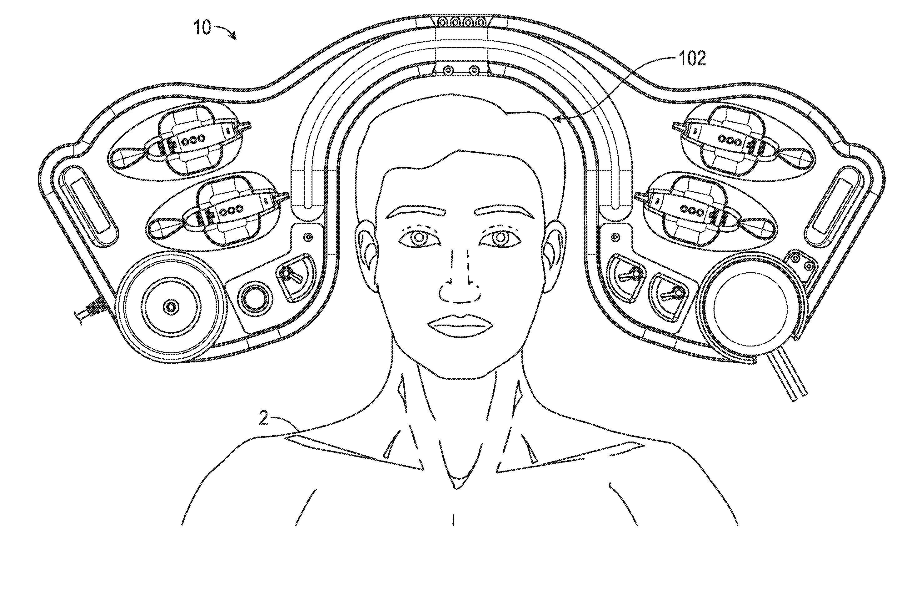
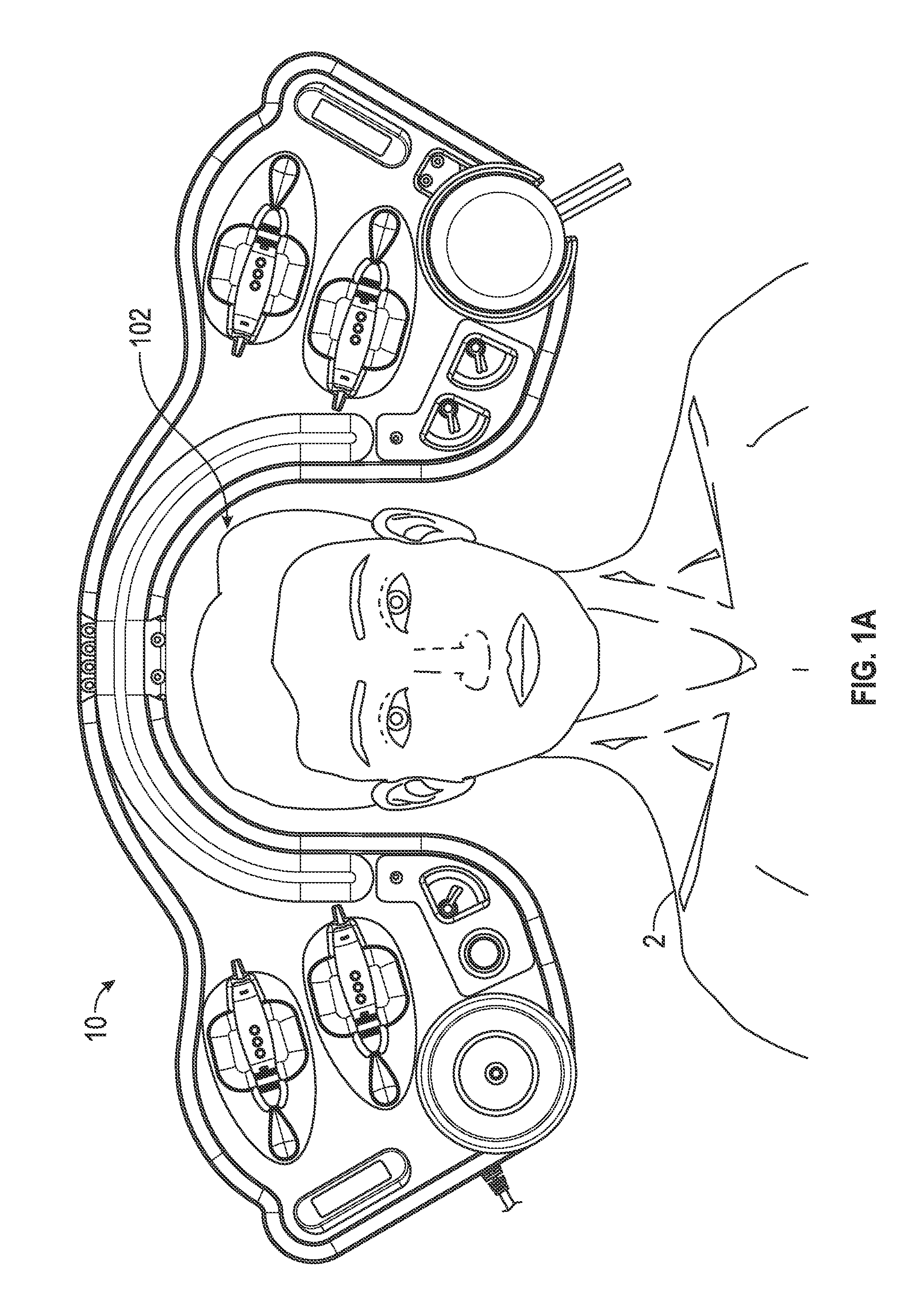
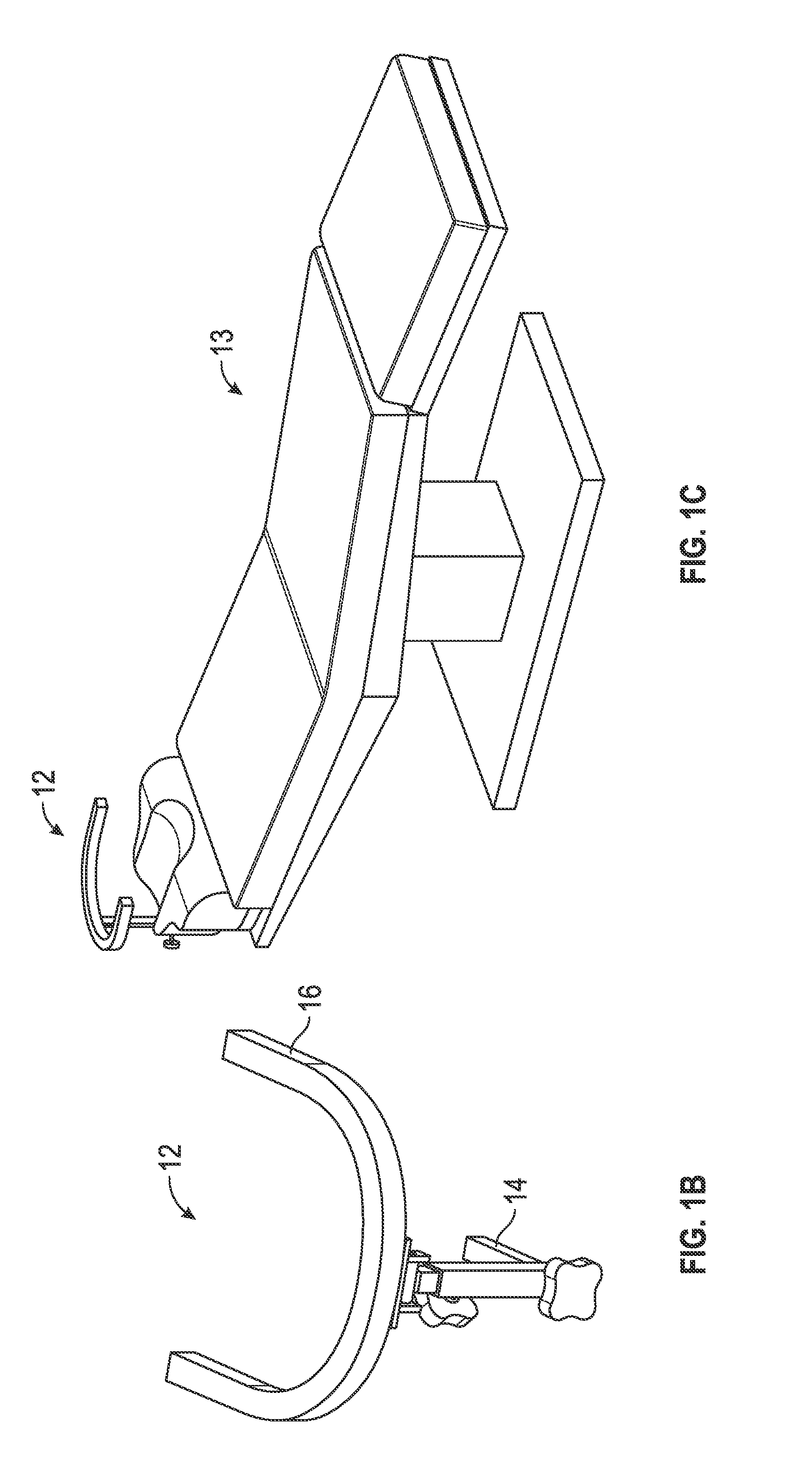
[0042]Although several embodiments, examples, and illustrations are disclosed below, it will be understood by those of ordinary skill in the art that the invention described herein extends beyond the specifically disclosed embodiments, examples, and illustrations and includes other uses of the invention and obvious modifications and equivalents thereof. Embodiments of the invention are described with reference to the accompanying figures, wherein like numerals refer to like elements throughout. The terminology used in the description presented herein is not intended to be interpreted in any limited or restrictive manner simply because it is being used in conjunction with a detailed description of certain specific embodiments of the invention. In addition, embodiments of the invention can comprise several novel features and no single feature is solely responsible for its desirable attributes or is essential to practicing the inventions herein described.

[0043]Some embodiments comprise...


PUM


Abstract

The disclosure herein provides ophthalmic surgical systems, methods, and devices. In one embodiment, a surgical apparatus for use by a surgeon during a surgical procedure comprises one or more sealed sterilized surgical packs configured to be disposed of after a single or a limited number of surgical procedures, the one or more sealed sterilized surgical packs comprising: a sterile surgical instrument; and a sterile surgical tray comprising a top surface configured to be part of a sterile field of the surgical procedure, the top surface comprising a receiving structure for positioning therein of the sterile surgical instrument, the sterile surgical tray further comprising walls that define a recess sized and configured to receive a reusable non-sterile module, the recess configured to encapsulate the reusable non-sterile module to isolate the reusable non-sterile module from the sterile field of the surgical procedure.

Description

CROSS-REFERENCE TO RELATED APPLICATIONS[0001]This application is a continuation-in-part of U.S. patent application Ser. No. 14 / 554,865, titled OPHTHALMIC SURGICAL SYSTEMS, METHODS, AND DEVICES, filed Nov. 26, 2014, which claims the benefit of U.S. Provisional Application No. 61 / 990,021, titled OPHTHALMIC SURGICAL SYSTEMS, filed May 7, 2014, and of U.S. Provisional Application No. 61 / 924,164, titled OPHTHALMIC SURGICAL SYSTEMS, filed Jan. 6, 2014, and of U.S. Provisional Application No. 61 / 910,112, titled OPHTHALMIC SURGICAL SYSTEMS, filed Nov. 28, 2013. This application also claims the benefit of U.S. Provisional Application No. 62 / 091,384, titled MULTI-USE SURGICAL TRAY SYSTEM, filed Dec. 12, 2014. Each of the foregoing applications is hereby incorporated by reference herein in its entirety.BACKGROUND[0002]1. Field[0003]The disclosure relates generally to the field of ophthalmic surgery, and more specifically to ophthalmic surgical systems, methods, and devices.[0004]2. Description...

Claims


Application Information

Patent Timeline
IPC IPC(8): A61B19/02A61B19/00A61B19/08A61F9/008
CPCA61B19/0256A61F9/008A61B19/56A61B19/5202A61B2019/0203A61B2017/00398A61B2217/007A61B2218/007A61B19/081A61F9/00736A61F9/00821A61B2017/00902A61B17/32002A61B2017/00477A61B2050/0051A61B90/50A61B50/20A61B50/30A61B50/33A61B2050/3008A61B46/00A61B90/20A61B2017/00115A61B2017/00207A61B2017/00367A61B2090/065A61B90/30A61B46/10
Inventor BRENNAN, JEFFREY DAVIDHUMAYUN, MARK
Owner ALCON INC
Learn More