
Touch sensing system and driving method thereof

a technology of touch sensing and driving method, which is applied in the direction of instruments, computing, electric digital data processing, etc., can solve the problems of difficult to improve the touch rate report and reduce the related art latency, and achieve the effect of reducing latency and improving touch report ra

Active Publication Date: 2015-04-23
LG DISPLAY CO LTD
View PDF3 Cites 12 Cited by
  • Summary
  • Abstract
  • Description
  • Claims
  • Application Information

AI Technical Summary

Benefits of technology

The present invention is a system and a method for improving touch sensing. The system can increase the number of touch reports and reduce the time it takes to detect touch. This makes it easier to use and more responsive.

Problems solved by technology

Accordingly, it is difficult to improve touch rate report and reduce latency in the related art.

Method used


Image

  • Touch sensing system and driving method thereof
  • Touch sensing system and driving method thereof
  • Touch sensing system and driving method thereof

Examples


Embodiment Construction

[0026]Hereinafter, exemplary embodiments of the present invention will be described in detail with reference to the accompanying drawings. Throughout the specification, like reference numerals denote substantially like components. Hereinafter, the detailed description of related known functions or configurations that may unnecessarily obscure the subject matter of the present invention in describing the present invention will be omitted.

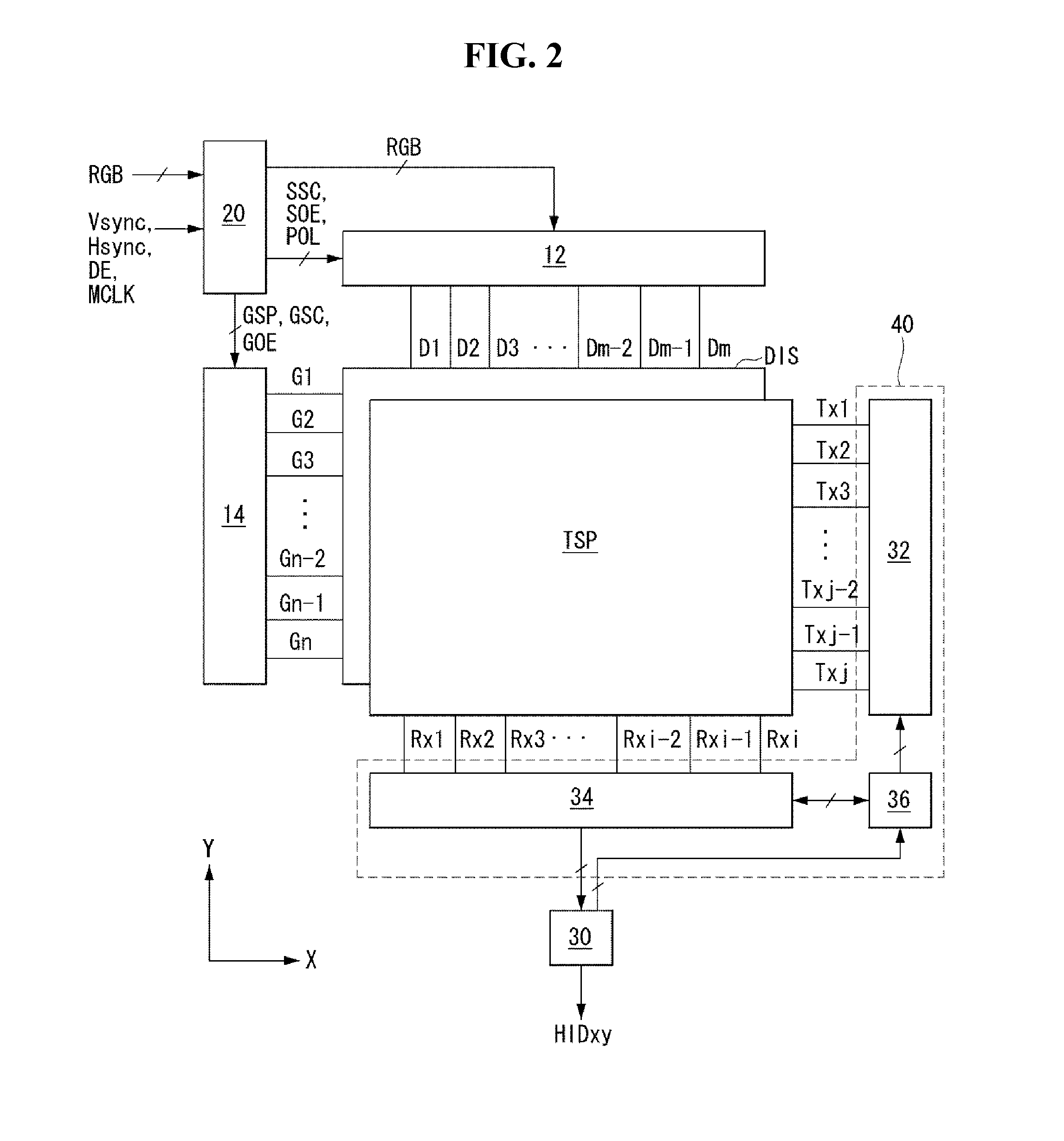
[0027]With reference to FIGS. 2 to 7, a touch sensing system of the present invention comprises a touch screen TSP, a touch screen drive circuit, etc.

[0028]The touch screen TSP may be bonded onto an upper polarizer POL1 of a display panel DIS, as shown in FIG. 4, or formed between the upper polarizer POL1 and upper substrate GLS1 of the display panel DIS, as shown in FIG. 5. As shown in FIG. 6, touch sensors on the touch screen TSP may be embedded in the in-cell type in a lower substrate, along with a pixel array, within the display panel DIS. In FIG...


PUM


Abstract

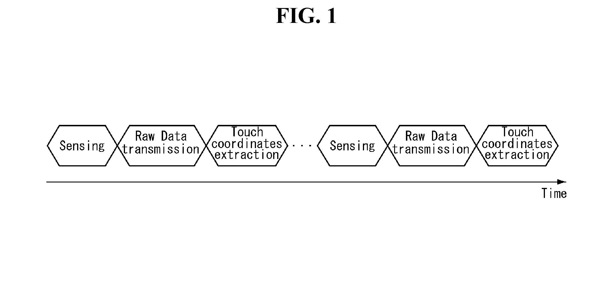
A touch sensing system and a driving method thereof are provided. The touch sensing system includes: a touch screen drive circuit which senses a change in the amount of electric charge in touch sensors during a sensing period, generates raw data and temporarily stores it in a buffer memory, transmits the raw data read out from the buffer memory to an algorithm execution unit during a raw data transmission period, and calculates the coordinates of touch input by the algorithm execution unit during an algorithm execution period. The touch screen drive circuit controls the amount of data stored in the buffer memory and the start timing of a read operation to make the sensing period and the raw data transmission period overlap each other.

Description

[0001]This application claims the benefit of Korea Patent Application No. 10-2013-0125190 filed on Oct. 21, 2013, which is incorporated herein by reference for all purposes as if fully set forth herein.BACKGROUND OF THE INVENTION[0002]1. Field of the Invention[0003]This document relates to a touch sensing system and a driving method thereof.[0004]2. Discussion of the Related Art[0005]User interface (UI) is configured so that users are able to communicate with various electronic devices and thus can easily and comfortably control the electronic devices as they desire. Examples of the user interface include a keypad, a keyboard, a mouse, an on-screen display (OSD), and a remote controller having an infrared communication function or a radio frequency (RF) communication function. User interface technologies have continuously evolved to increase user's sensibility and handling convenience. The user interface has been recently developed to include touch UI, voice recognition UI, 3D UI, e...

Claims


Application Information

Patent Timeline
Patent Type & Authority Applications(United States)
IPC IPC(8): G06F3/041
CPCG06F3/0416G06F3/044G06F3/0446G06F3/04166
Inventor SHIN, MYUNGHOLIM, DONGKYUNYOON, SEUNGHWAN
Owner LG DISPLAY CO LTD
Learn More