
Key module and keyboard having the same

Active Publication Date: 2015-04-16
LITE ON ELECTRONICS (GUANGZHOU) LTD +1
View PDF3 Cites 21 Cited by
  • Summary
  • Abstract
  • Description
  • Claims
  • Application Information

AI Technical Summary

Benefits of technology

The present invention relates to a keyboard keycap that has unique features and advantages. The keycap has four pivot joints that allow for rotational and no translational motion, simplifying assembly and reducing lateral movement. The keycap can move quickly and smoothly up and down relative to the base, making it easier to type on the keyboard. The force distribution across the keycap is even, making it more rigid and less prone to tilting, which reduces the need for stabilizer links and makes assembly easier. The keycap also has uniform rigidity and resilience to touch and press, making it more comfortable for users.

Problems solved by technology

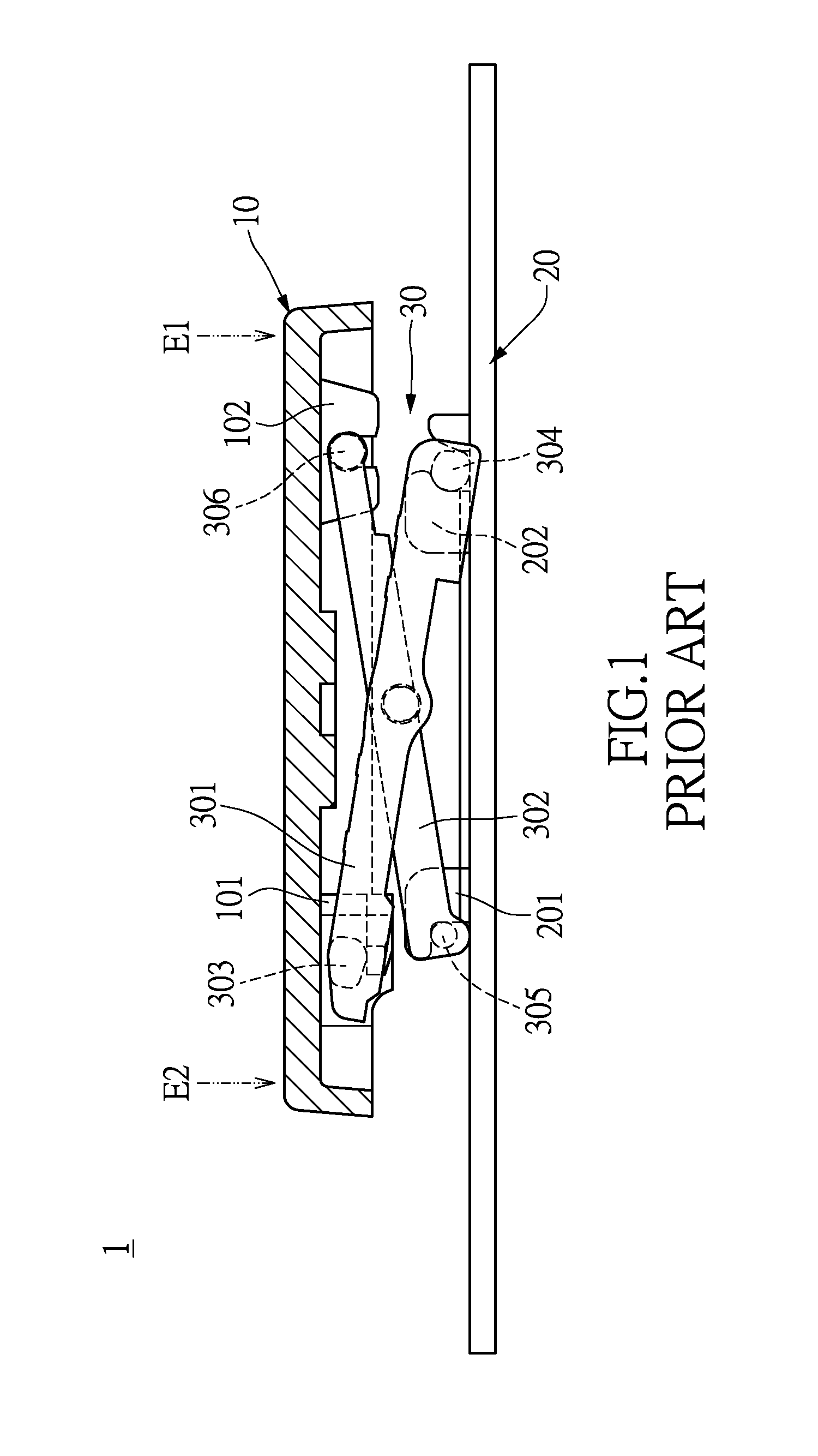
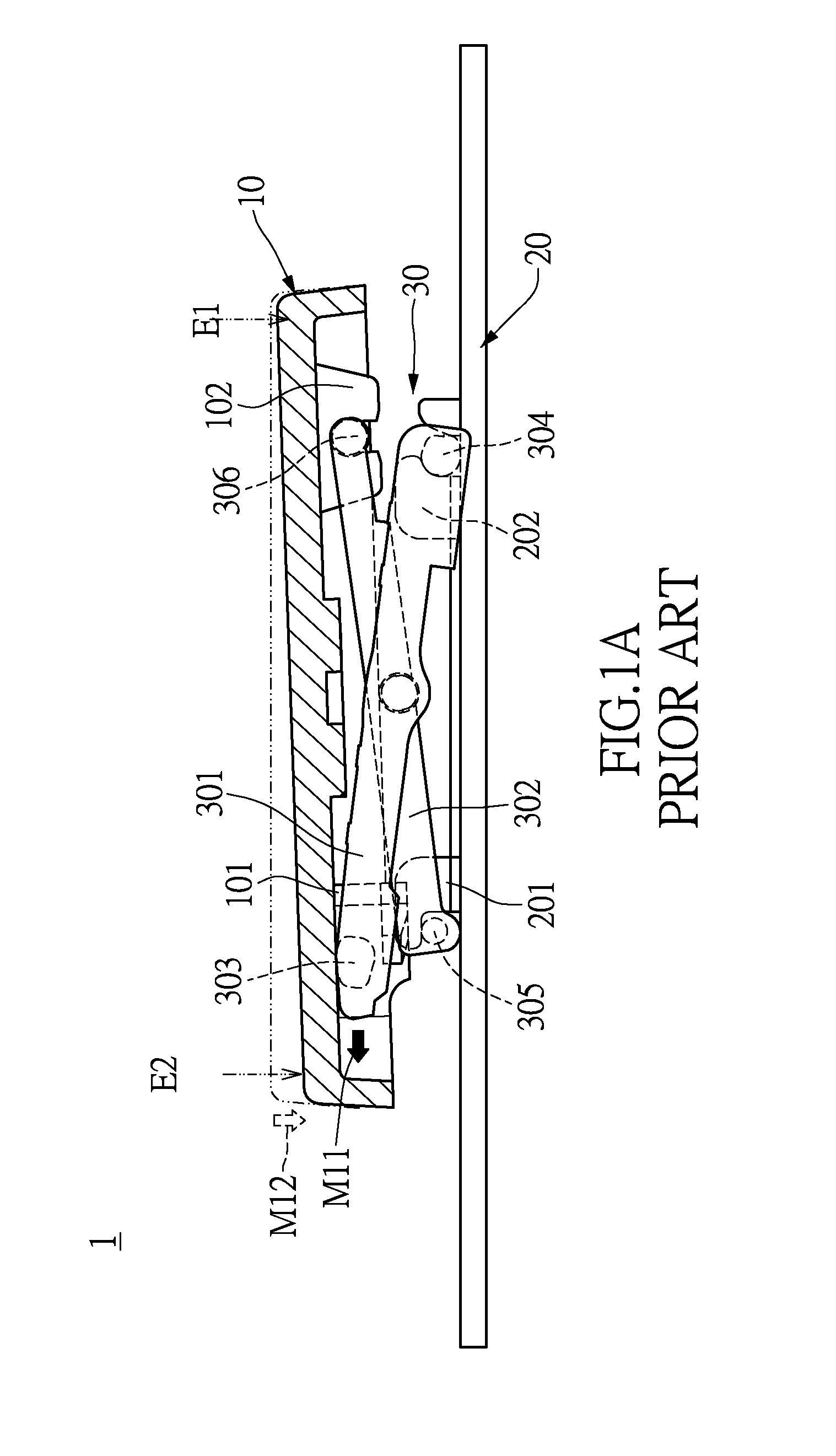
The transverse movement reduces the effective vertical travel distance of the key structure, such that the requirement of small thickness is not met for slim or super slim keyboards.
Additionally, given that the force applied on the keycap 10 is not evenly distributed across the entire keycap 10, the key structure easily becomes tilted and unstable, even unable to complete the motion for driving the scissor structure 30, such that the switch cannot be triggered and more noise is created during operation.
Moreover, when the conventional key structure 1 is applied on super slim keyboards, given that the ineffective distance of the sliding end E2 of the keycap 10 is overly long, the effective vertical travel distance is insufficient.
As a result, electrical conduction is poor and undesirable tilting of corners of the keycap 10 is more serious, rendering the key structure 1 less suitable for super slim keyboards.
As can be seen, using human labor for assembly not only compromises the speed of assembly but also increases the rate of poor assemblies.
Additionally, the force of assembly is not easily controlled, which leads to damages to the keycap 10 or the scissor structure 30.
Therefore, the assembly of the keycap 10 and the scissor structure 30 requiring human labor cannot be automated and the production speed cannot be increased.
Additionally, additional metal stabilizer links 40 not only creates serious noise during operation, but also complicates assembly, and increases the rate of poor quality and cost of human labor.

Method used


Image

  • Key module and keyboard having the same
  • Key module and keyboard having the same
  • Key module and keyboard having the same

Examples


Embodiment Construction

[0025]The aforementioned illustrations and following detailed descriptions are exemplary for the purpose of further explaining the scope of the present disclosure. Other objectives and advantages related to the present disclosure will be illustrated in the subsequent descriptions and appended drawings.

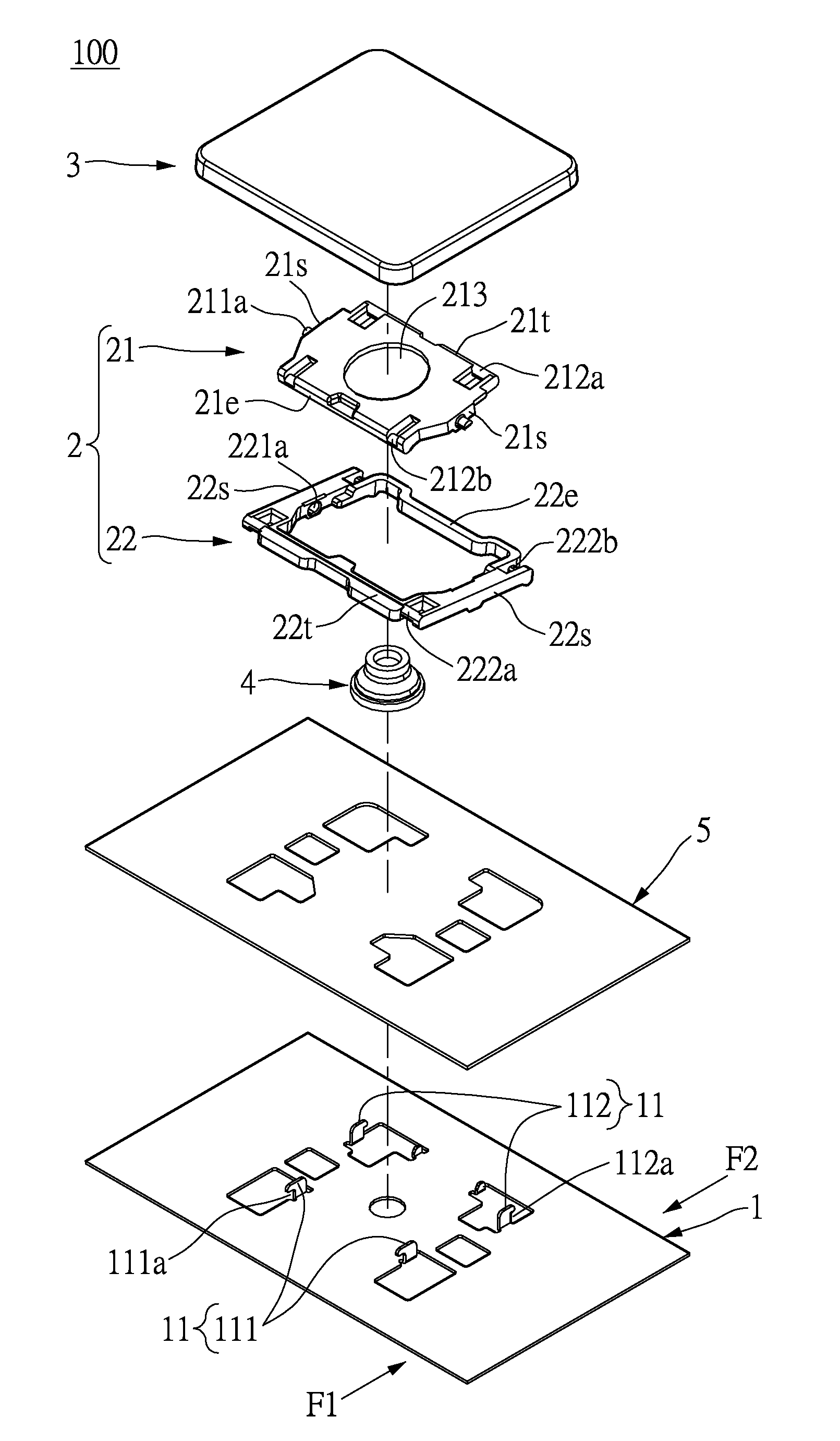
[0026]Unless otherwise specified, the present disclosure is not limited to any mention of quantities or the like in the following description of embodiments. The details disclosed herein are not limiting and serve only as a basis of the application scope and as an exemplary basis for teaching someone skilled in the art to apply the present disclosure in any form or method, including using the features disclosed herein or possible undisclosed combinations thereof. Additionally, languages referring to directions such as left, right, front and rear, etc. refer only to the directions in the figures and serve as descriptions instead of limitations of the present disclosure. A key module 100...


PUM


Abstract

A key module and a keyboard having the key module are provided. The key module includes a base, a scissor-type unit and a keycap. The scissor-type unit has a first frame and a second frame. The first frame has a connection shaft rotatably pivotally connected to a shaft hole of the second frame. The shaft hole has a travel distance therein for the shaft to move within the shaft hole along a predetermined direction. The first and second frames respectively have a first side pivotally connected to a pivot connection unit of the key cap, and a second side slidably connected to a restricting unit of the base. Through the above-mentioned design, the first frame can rotate with respect to the second frame, so that the keycap can move up and down with respect to the base.

Description

BACKGROUND OF THE INVENTION[0001]1. Field of the Invention[0002]The present disclosure relates to a key module and a keyboard having the same; in particular, to a key module which evenly supports a keycap while preventing tilting of the keycap and is suitable for slim keyboards, and a slim keyboard having the same.[0003]2. Description of Related Art[0004]The demand for slim computers (e.g. laptops) calls for keyboards using scissor-type structures which guides the up and down movement of the keycaps and balances the force applied by the user on each key. As shown in FIG. 1, the keycap 10 of a conventional key structure 1 has a first sliding joint 101 and a first pivot joint 102. The base 20 has a second sliding joint 201 and a second pivot joint 202. Scissor structure 30 (scissor switch) includes a first support unit 301 and a second support unit 302. The first support unit 301 is pivotally connected to the second support structure 302. The first support structure 301 has a first sl...

Claims


Application Information

Patent Timeline
IPC IPC(8): H01H13/02H01H13/70
CPCH01H13/02H01H13/70H01H3/125
Inventor CHEN, CHUN-LIN
Owner LITE ON ELECTRONICS (GUANGZHOU) LTD
Learn More