
Driving methods for color display device

a technology of color display device and driving method, which is applied in the direction of instruments, computing, electric digital data processing, etc., can solve the problems of inacceptable choice of display device, and inability to accurately detect the color

Active Publication Date: 2015-04-09
E INK CORPORATION
View PDF7 Cites 143 Cited by
  • Summary
  • Abstract
  • Description
  • Claims
  • Application Information

AI Technical Summary

Benefits of technology

The present invention provides a driving method for an electrophoretic display that can display multiple colors using different types of pigment particles. The method includes steps of applying a first driving voltage to a pixel in the display for a first period of time to drive the pixel towards the color state of the first type of pigment particles, applying a second driving voltage to the pixel for a second period of time to drive the pixel towards the color state of the second type of pigment particles, and repeating these steps. The method ensures that the three types of pigment particles have optical characteristics that differ from one another, and the first and second driving voltages have opposite charge polarities. The method also includes a shaking waveform before the first driving voltage is applied, and a driving step to the full color state of the first type of pigment particles after the shaking waveform. The method is voltage insensitive, meaning that the display can display multiple colors without being affected by changes in voltage.

Problems solved by technology

The biggest disadvantage of such a technique is that since each of the sub-pixels has a reflectance of about one third (⅓) of the desired white state, the white state is fairly dim.
Brighter colors can be achieved by adding light from the white pixel, but this is achieved at the expense of color gamut to cause the colors to be very light and unsaturated.
Even with these approaches, the white level is normally substantially less than half of that of a black and white display, rendering it an unacceptable choice for display devices, such as e-readers or displays that need well readable black-white brightness and contrast.

Method used


Image

  • Driving methods for color display device
  • Driving methods for color display device
  • Driving methods for color display device

Examples


example

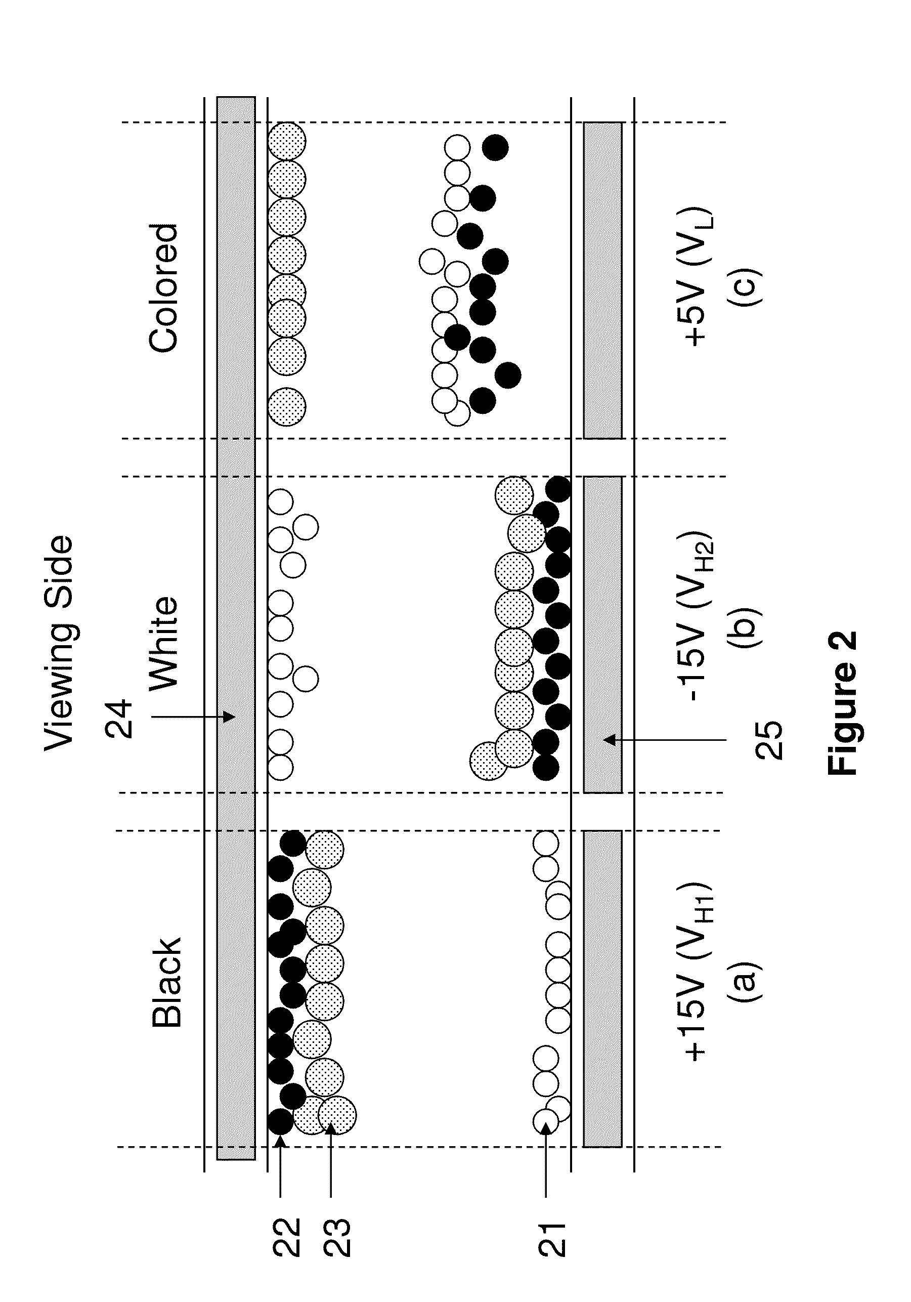
[0099]This example is demonstrated in FIG. 2. The white pigment particles (21) are negatively charged while the black pigment particles (22) are positively charged, and both types of the pigment particles are smaller than the colored particles (23).

[0100]The colored particles (23) carry the same charge polarity as the black particles, but are slightly charged. As a result, the black particles move faster than the colored particles (23) under certain driving voltages.

[0101]In FIG. 2a, the applied driving voltage is +15V (i.e., VH1). In this case, the white particles (21) move to be near or at the pixel electrode (25) and the black particles (22) and the colored particles (23) move to be near or at the common electrode (24). As a result, the black color is seen at the viewing side. The colored particles (23) move towards the common electrode (24) at the viewing side; however because their lower charge intensity and larger size, they move slower than the black particles.

[0102]In FIG. 2...


PUM

PropertyMeasurementUnit
timeaaaaaaaaaa
timeaaaaaaaaaa
voltageaaaaaaaaaa

Abstract

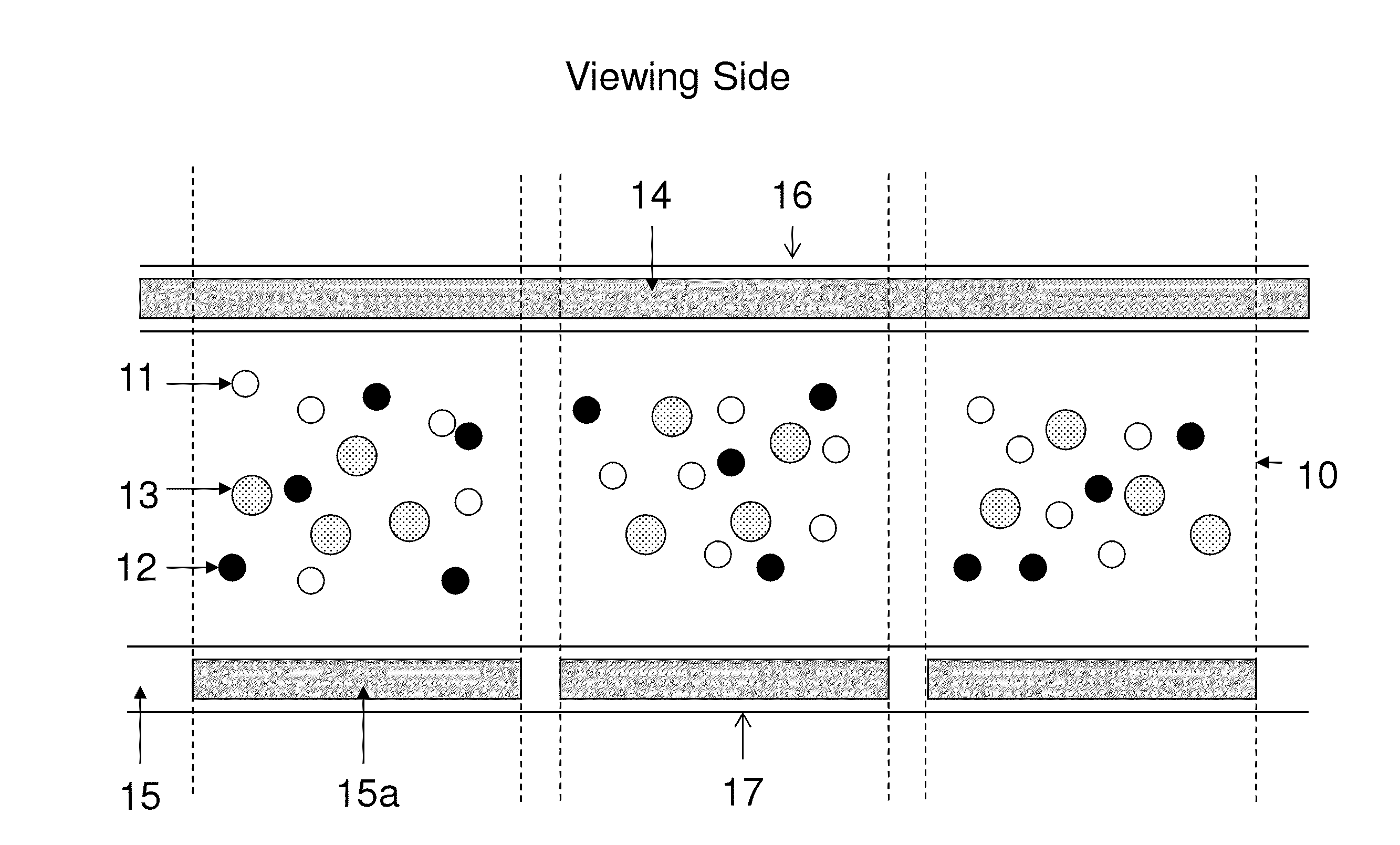
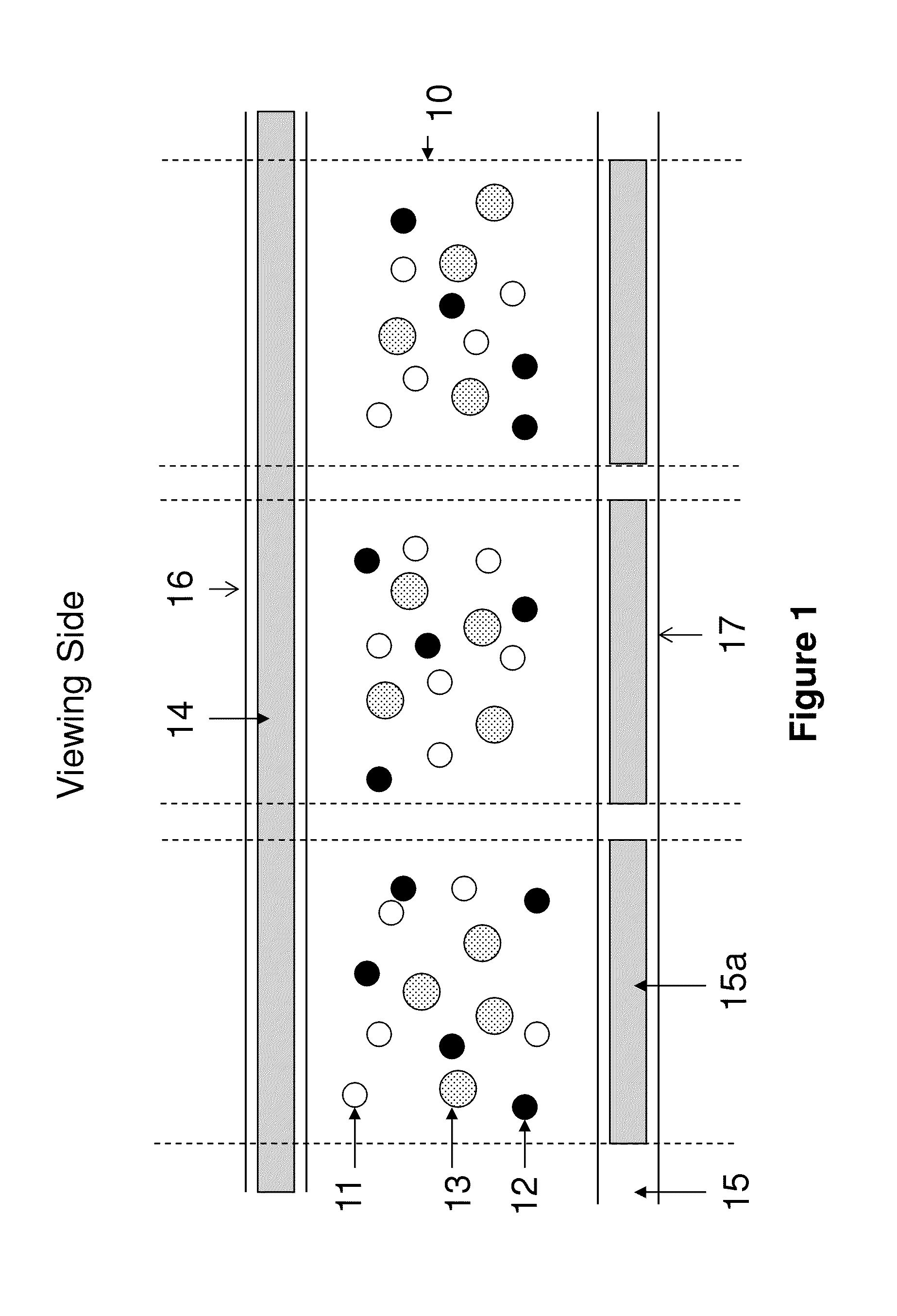
The present invention is directed to driving methods for a color display device which can display high quality color states. The display device utilizes an electrophoretic fluid which comprises three types of pigment particles having different optical characteristics.

Description

[0001]This application claims the benefit of U.S. Provisional Application Nos. 61 / 887,821, filed Oct. 7, 2013; 61 / 925,055, filed Jan. 8, 2014; 61 / 942,407, filed Feb. 20, 2014; 61 / 979,464, filed Apr. 14, 2014; and 62 / 004,713, filed May 29, 2014. The contents of the above-identified applications are incorporated herein by reference in their entireties.FIELD OF THE INVENTION[0002]The present invention is directed to driving methods for color display devices to display high quality color states.BACKGROUND OF THE INVENTION[0003]In order to achieve a color display, color filters are often used. The most common approach is to add color filters on top of black / white sub-pixels of a pixellated display to display the red, green and blue colors. When a red color is desired, the green and blue sub-pixels are turned to the black state so that the only color displayed is red. When a blue color is desired, the green and red sub-pixels are turned to the black state so that the only color displayed ...

Claims


Application Information

Patent Timeline
Patent Type & Authority Applications(United States)
IPC IPC(8): G09G3/34G09G3/20
CPCG09G3/344G09G3/2003G09G2320/0242G09G2310/0262G09G2310/068G09G2300/0452G02F2001/1678G09G2320/0204
Inventor LIN, CRAIGHUANG, JO-CHENGCHEN, HENG-CHELAXTON, PETERWANG, MINGCHENG, PING-YUEHZANG, HONGMEI
Owner E INK CORPORATION
Learn More