Electrical connector

a technology of electrical connectors and connectors, applied in the direction of electrical apparatus, connection, coupling device connection, etc., can solve the problems of poor structural strength and achieve the effect of enhancing structural strength

Active Publication Date: 2015-04-02
BELLWETHER ELECTRONIC CORP
View PDF5 Cites 4 Cited by
  • Summary
  • Abstract
  • Description
  • Claims
  • Application Information

AI Technical Summary

Benefits of technology

[0006]Therefore, the present invention is to provide an electrical connector having an extension plate extended directly outwards from a front end surface of the male connector body, so that the top surface of the extension plate and the top surface of the male connector body form a linear plane, enhancing the structural strength between the extension plate and the male connector body.
[0009]1. A quick and easy assembling effect can be achieved by the design of latching the hook with the latch edge.
[0011]3. The cross-sectional area of the positioning block is smaller than the cross-sectional area of the positioning notch, as the positioning block has a guiding corner for guiding the male connector body to slide into the accommodating space of the female connector successfully and easily to achieve a quick precise assembling effect.

Problems solved by technology

Because each elastic arm is in a slender strip shape, the structural strength is poor, as the elastic wall may be easily broken off from the male connector body when the each elastic arm is flipped.

Method used


Image

  • Electrical connector
  • Electrical connector
  • Electrical connector

Examples


Embodiment Construction

[0020]The technical contents of the present invention will become apparent with the detailed description of preferred embodiments accompanied with the illustration of related drawings as follows. It is noteworthy that same numerals are used for representing same respective elements in the drawings.

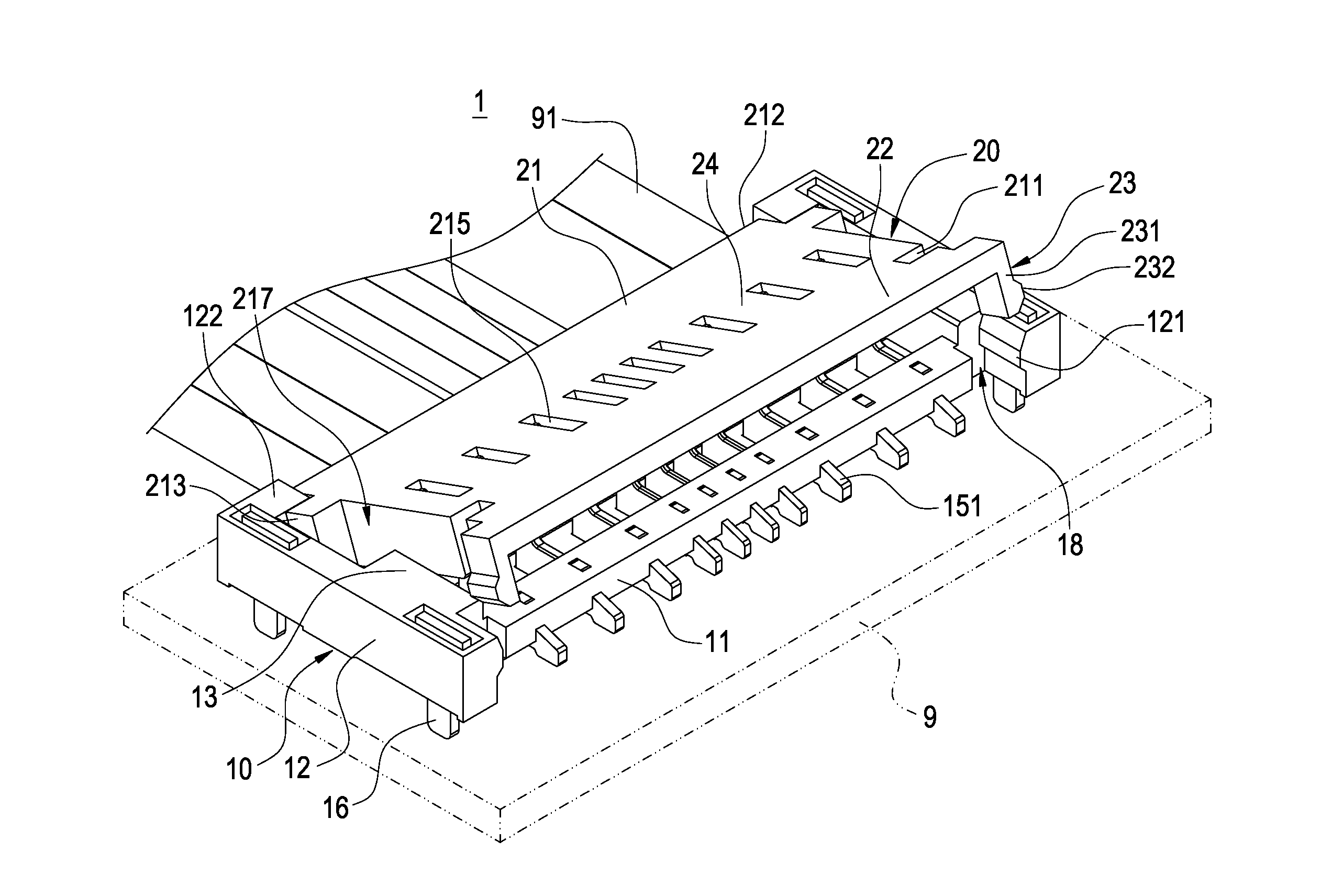
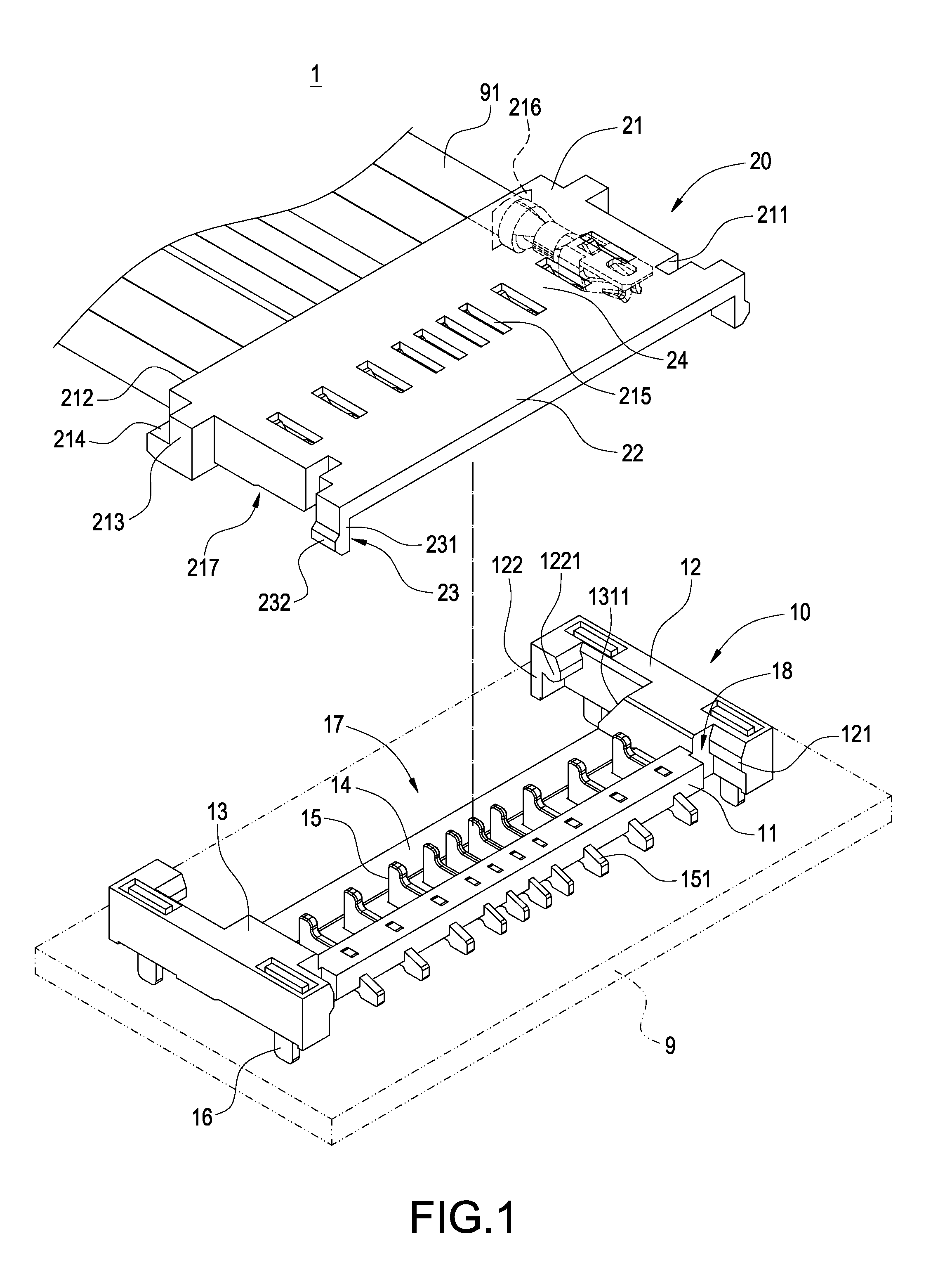
[0021]With reference to FIGS. 1 and 2 for an exploded view of an electrical connector 1 of the present invention and a schematic view of a male connector of the present invention, the electrical connector 1 comprises a female connector 10 and a male connector 20.

[0022]The female connector 10 includes a female connector body 11, a pair of vertical walls 12, a pair of positioning blocks 13, a backplane 14, a plurality of conductive plates 15 and a plurality of fixing pins 16. The pair of vertical walls 12 are coupled to both ends of the female connector body 11 respectively and define an accommodating space 17 between the pair of vertical walls 12; each positioning block 13 is protruded from...


PUM


Abstract

An electrical connector includes a female connector (10) and a male connector (20). The female connector (10) includes a female connector body (11) and a vertical wall (12) that define an accommodating space (17), a positioning block (13) disposed in the accommodating space (17), a latch edge (121) and a blocking wall (122) protruded from the vertical wall (12), and a latch space (18) defined by the latch edge (121) and female connector body (11). The male connector (20) having front, rear, and side end surfaces (211, 212, 213) is plugged into the accommodating space (17) and includes a male connector body (21), an extension plate (22), and a hook (23) latched to the latch edge (121), and the rear end surface (212) abuts the blocking wall (122), and the side end surface (213) has a positioning notch (217) for positioning the positioning block (13).

Description

FIELD OF THE INVENTION[0001]The present invention relates to an electrical connector, particularly to a wire-to-board electrical connector.BACKGROUND OF THE INVENTION[0002]In the field of electronic products, signals are transmitted through a conductive wire or a printed circuit installed on a circuit board. If it is necessary to transmit the signals from the conductive wire to a printed circuit of the circuit board or vice versa, the two are generally electrically coupled to each other through a wire-to-board electrical connector for convenient assembling.[0003]In general, the electrical connector includes a female connector and a male connector, wherein the former has an accommodating space and a pair of latch edges; the latter includes a male connector body, a pair of elastic arms extended from the male connector body and disposed with an interval therebetween, and a hook extended from each elastic arm. When used, the male connector is installed into the accommodating space of th...

Claims


Application Information

Patent Timeline
Patent Type & Authority Applications(United States)
IPC IPC(8): H01R13/627H01R13/405
CPCH01R13/405H01R13/6275H01R13/6273H01R12/75
Inventor CHEN, KUAN-WULEE, HSING-YU
Owner BELLWETHER ELECTRONIC CORP
Why Eureka
Try Eureka