
Image inspection result determination apparatus, image inspection system, method of determinating image inspection result, and storage medium

a technology of image inspection and result determination, applied in the direction of image enhancement, instruments, printing, etc., can solve the problems of incorrect method position matching, inefficient generation of master image from printed product as reference image, and inability to achieve accurate position matching

Active Publication Date: 2015-03-19
RICOH KK
View PDF8 Cites 69 Cited by
  • Summary
  • Abstract
  • Description
  • Claims
  • Application Information

AI Technical Summary

Benefits of technology

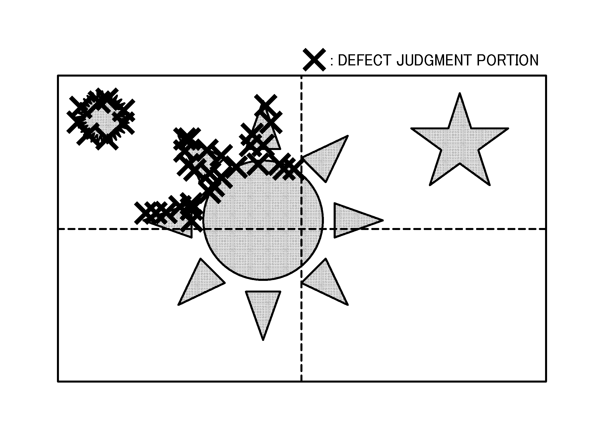
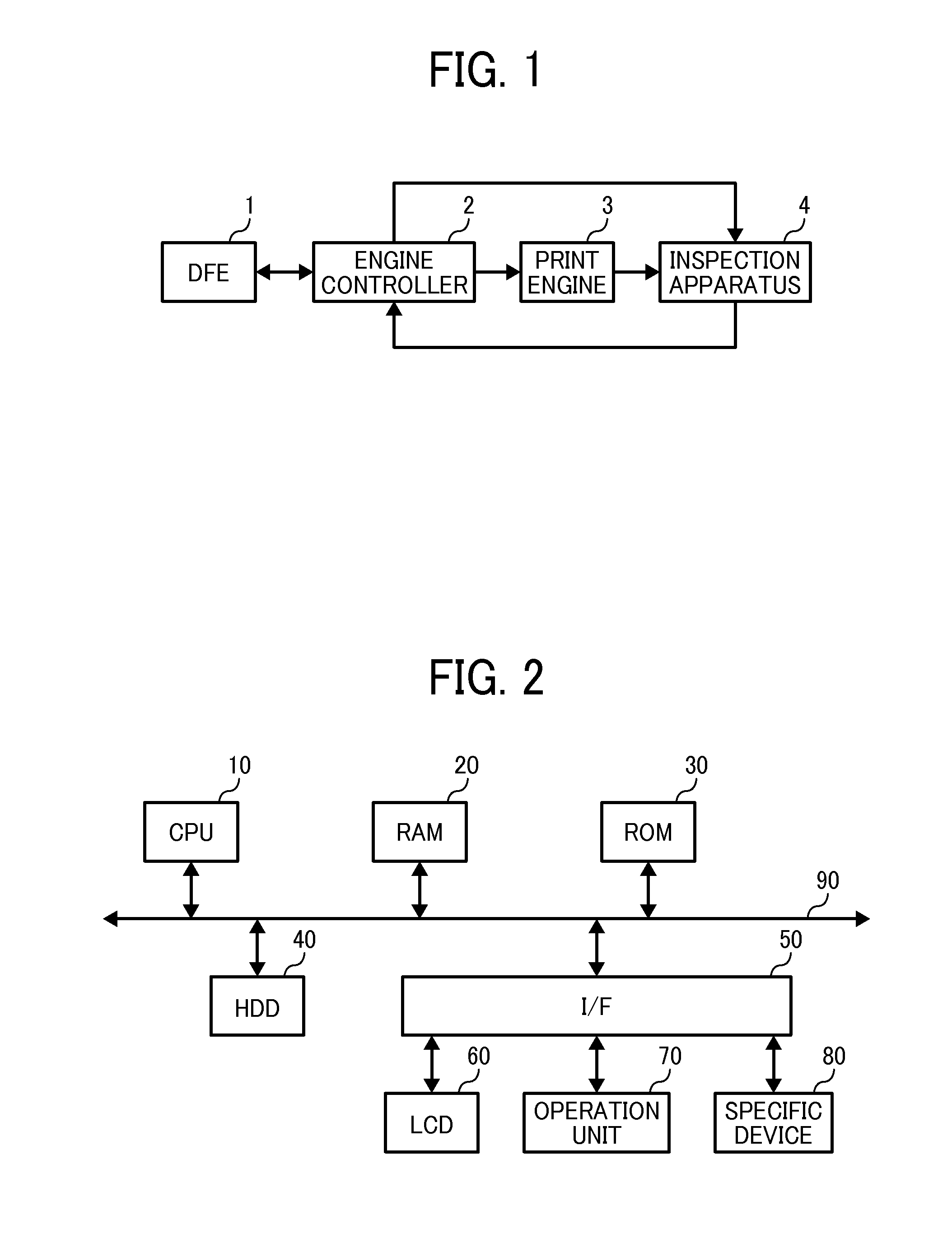
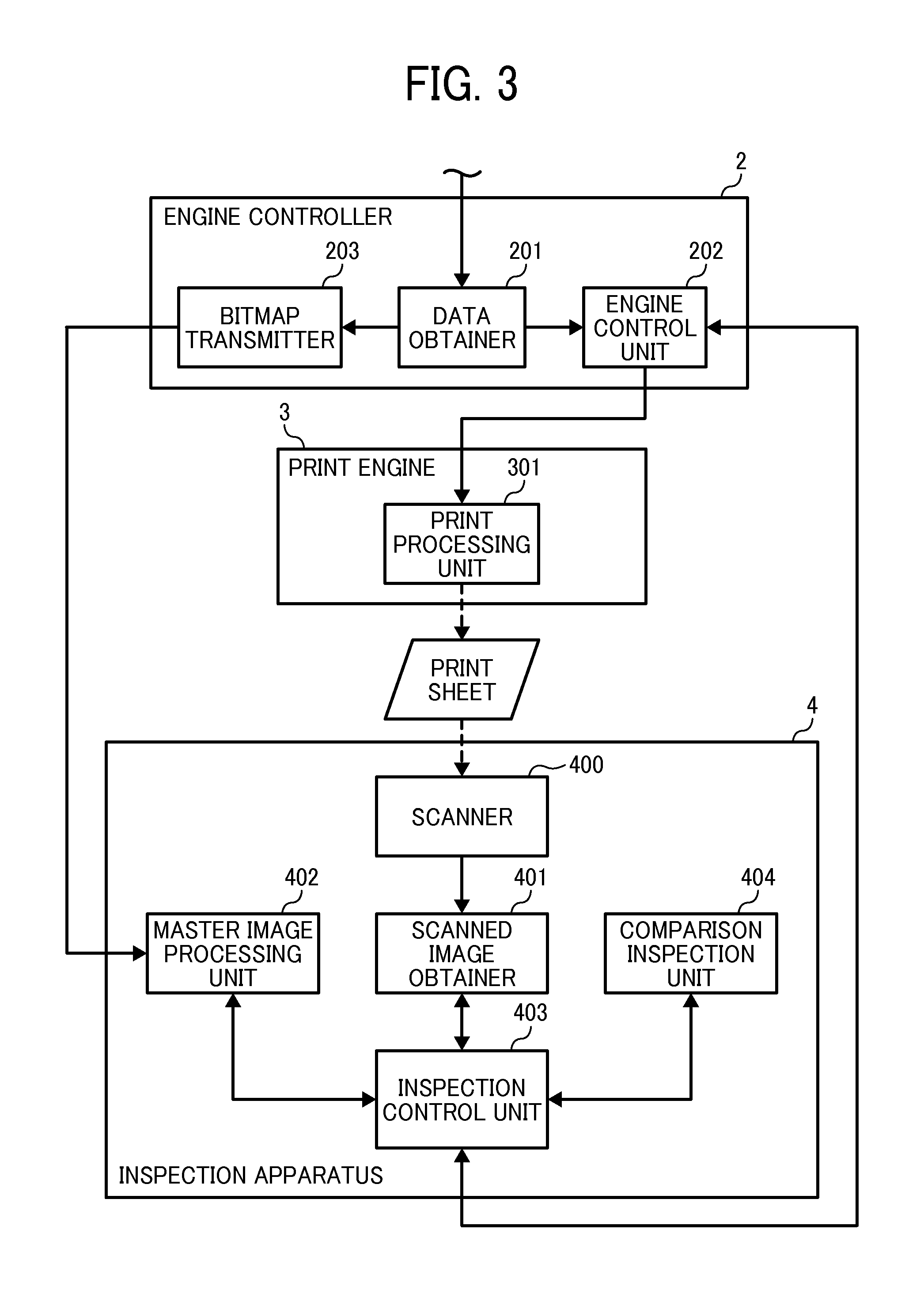
The present invention provides an apparatus and method for verifying inspection results of scanned images of printed sheets. The apparatus includes an inspection result obtaining unit to obtain inspection result information indicating defect amount and defect position in the scanned image, from an inspection result of defect judgment of the scanned image with respect to an inspection reference image. The apparatus also includes a verification unit to count defect amount occurring to the scanned image for each of the areas based on the obtained inspection result information, to determine whether a defect pattern occurring to the scanned image matches a pre-set condition corresponding to a false defect detection condition causable by failure of the position matching. The technical effect of the invention is to improve the accuracy of inspection results and prevent false detections caused by position matching failures.

Problems solved by technology

Printing apparatuses of digital type, not using a press plate, such as image forming apparatuses using electrophotography typically print images with a small volume, and also print different images for each page (i.e., variable printing), in which generation of a master image from a printed product as a reference image is not efficient.
However, even if the position matching is conducted, the position matching may not be conducted correctly.
For example, when the same image pattern is repeatedly drawn, the above position matching method may conduct false position matching.

Method used


Image

  • Image inspection result determination apparatus, image inspection system, method of determinating image inspection result, and storage medium
  • Image inspection result determination apparatus, image inspection system, method of determinating image inspection result, and storage medium
  • Image inspection result determination apparatus, image inspection system, method of determinating image inspection result, and storage medium

Examples


Embodiment Construction

[0029]A description is now given of exemplary embodiments of the present invention. It should be noted that although such terms as first, second, etc. may be used herein to describe various elements, components, regions, layers and / or sections, it should be understood that such elements, components, regions, layers and / or sections are not limited thereby because such terms are relative, that is, used only to distinguish one element, component, region, layer or section from another region, layer or section. Thus, for example, a first element, component, region, layer or section discussed below could be termed a second element, component, region, layer or section without departing from the teachings of the present invention.

[0030]In addition, it should be noted that the terminology used herein is for the purpose of describing particular embodiments only and is not intended to be limiting of the present invention. Thus, for example, as used herein, the singular forms “a”, “an” and “the...


PUM


Abstract

An apparatus for verifying an inspection result includes an inspection result obtaining unit to obtain inspection result indicating defect amount and defect position in a scanned image, from an inspection result of defect judgment of the scanned image with respect to an inspection reference image, the defect judgment being performed through dividing at least one of the scanned image and the inspection reference image and conducting position matching of the scanned image and inspection reference image; and a verification unit to count defect amount occurring to the scanned image, to determine whether a defect pattern occurring to the scanned image matches a pre-set condition corresponding to a false detection condition causable by failure of the position matching, and to determine that defect occurring to the scanned image is a false detection when the counted defect amount is a threshold or more, and the defect pattern matches the false detection condition.

Description

CROSS-REFERENCE TO RELATED APPLICATION[0001]This application claims priority pursuant to 35 U.S.C. §119(a) to Japanese Patent Application No. 2013-191612, filed on Sep. 17, 2013 in the Japan Patent Office, the disclosure of which are incorporated by reference herein in their entirety.BACKGROUND[0002]1. Technical Field[0003]The present invention relates to an image inspection result determination apparatus, an image inspection system, and an image inspection result determination method, and more particularly to determination of failure of position matching for an image comparison inspection.[0004]2. Background Art[0005]Conventional inspections of printed products such as printed papers are conducted by visual inspection, but inspection apparatuses have been introduced to conduct the inspection as a post-processing operation of an offset printing. As to the inspection apparatus, the printed products are visually inspected by an operator to select a printed product having satisfactory ...

Claims


Application Information

Patent Timeline
Patent Type & Authority Applications(United States)
IPC IPC(8): G06T7/00
CPCG06T7/0008G06T7/001G06T2207/30144G06T2207/30168G06T2207/10008G06T2207/20021B41F33/0036H04N1/00002
Inventor FUKASE, TAKAHIRO
Owner RICOH KK
Learn More