Expandable and adjustable lordosis interbody fusion system

Active Publication Date: 2015-03-05
ADCURA INC
View PDF4 Cites 86 Cited by
  • Summary
  • Abstract
  • Description
  • Claims
  • Application Information

AI Technical Summary

Benefits of technology

The present invention is a device for in situ adjustment during spine surgery. It allows the surgeon to expand the fusion cage and adjust the lordotic angle of the cage while in place. The device also allows for the introduction of bone graft material at the operation site while the device is in place. This geometrically variable device accommodates the spinal condition of each patient. The technical effects of this invention include improved spine surgery outcomes and reduced surgery duration and recovery time.

Problems solved by technology

It is unlikely that these values can be determined precisely prior to the operation, which is a drawback in present procedures.
Present lateral interbody fusion cage devices are generally limited to providing height expansion functions, but not a lordotic adjustment capability.
In implementing a trial-and-error approach to sizing and fitting the interbody fusion cage into the target region for the particular geometric configuration for that patient, the patient is subjected to significant invasive activity.

Method used


Image

  • Expandable and adjustable lordosis interbody fusion system
  • Expandable and adjustable lordosis interbody fusion system
  • Expandable and adjustable lordosis interbody fusion system

Examples


Embodiment Construction

.

BRIEF DESCRIPTION OF THE DRAWING FIGURES

[0014]An embodiment of the present invention is described herein with reference to the following drawing figures, with greater emphasis being placed on clarity rather than scale:

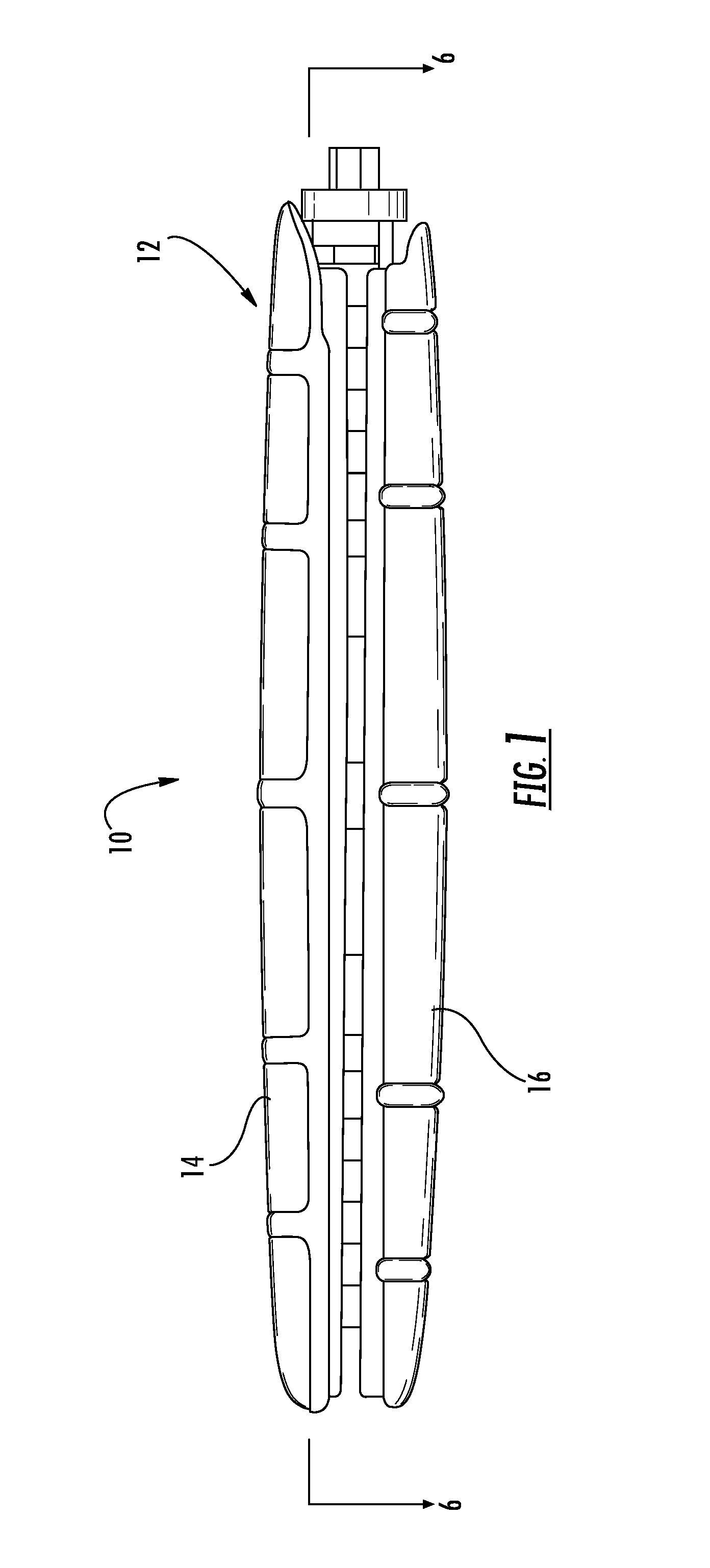
[0015]FIG. 1 is a view in side elevation from the side of the expandable shell device.

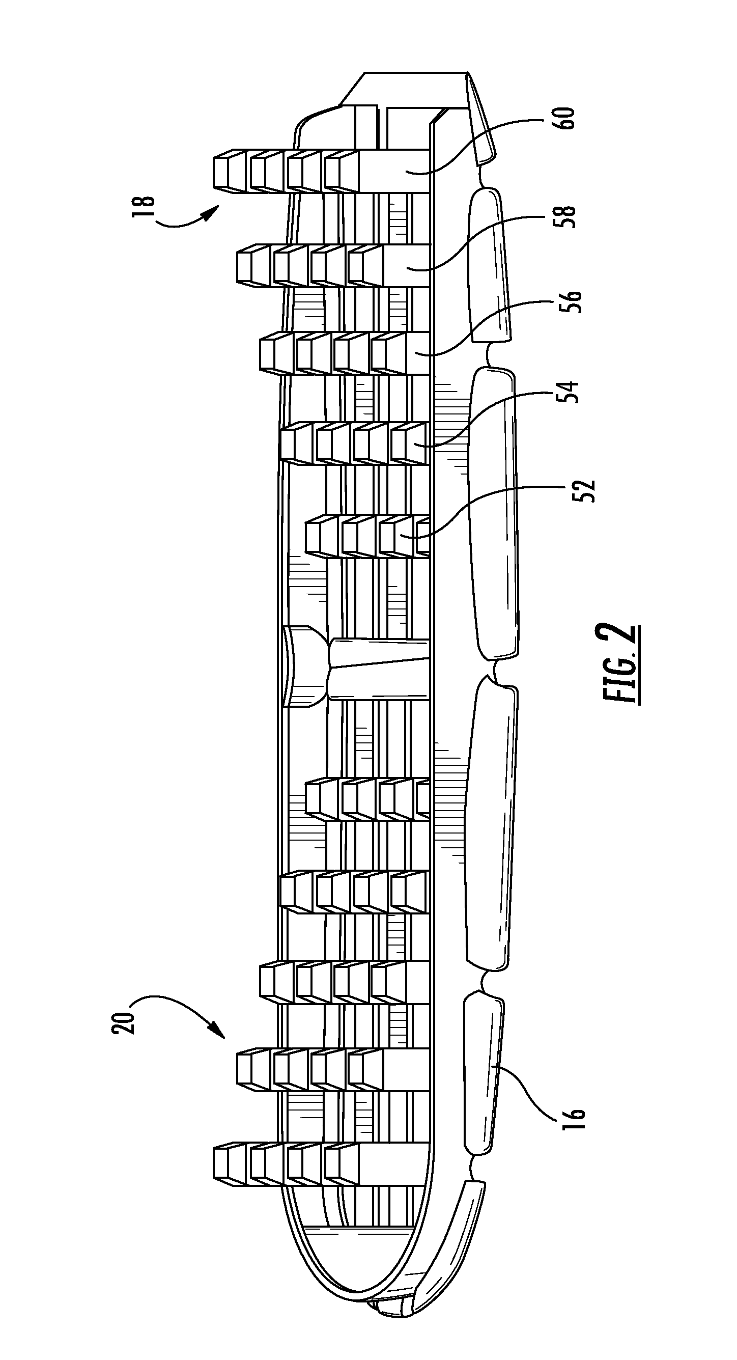
[0016]FIG. 2 is a perspective view of a bottom section of the expandable shell.

[0017]FIG. 3 is a top plan view of the bottom section of the expandable shell.

[0018]FIG. 4 is a top plan view of the expandable shell device.

[0019]FIG. 5 is a perspective view of a tapered external helical threaded member.

[0020]FIG. 5A is a view in side elevation from the side of the tapered external helical threaded member.

[0021]FIG. 5B is a view in side elevation from the front of the tapered external helical threaded member.

[0022]FIG. 6 is a cross-sectional view of the device taken along lines 6-6 in FIG. 1.

[0023]FIGS. 7A-7C are a series of views in side elevation of the device as it undergoes expansion...


PUM


Abstract

An expandable housing for an interbody fusion system has movable tapered external helical threaded members that travel along tracking to operably engage against the top and bottom shell members, urging them apart to cause expansion in the height of the housing. In an embodiment, the tapered members are disposed in a dual arrangement such that independent engagement of the tapered members along lateral portions of the top and bottom shells cause an angular tilt to the exterior surface of the housing when the tapered members are moved to different degrees. This function permits adjustment in the angular relationship between adjacent vertebrae and assists the lordotic adjustment of the patient's spine. When the functions of the device are used in combination by the surgeon, the device provides an effective tool for in situ adjustment when performing lateral lumbar interbody fusion.

Description

RELATED APPLICATIONS[0001]The present U.S. non-provisional patent application is related to and claims priority benefit to an earlier-filed provisional patent application titled EXPANDABLE LATERAL INTERBODY FUSION SYSTEM, Ser. No. 61 / 871,780, filed Aug. 29, 2013. The identified earlier-filed application is hereby incorporated by reference into the present application as though fully set forth herein.FIELD OF THE INVENTION[0002]The invention relates to surgical procedures and apparatus for treating lumbar back pain.BACKGROUND OF THE INVENTION[0003]Lumbar spinal fusion is a surgical procedure to correct problems relating to the human spine. It generally involves removing damaged disc and bone from between two vertebrae and inserting bone graft material that promotes bone growth. As the bone grows, the two vertebrae join, or fuse, together. Fusing the bones together can help make that particular area of the back more stable and help reduce problems related to nerve irritation at the si...

Claims


Application Information

Patent Timeline
IPC IPC(8): A61F2/44A61F2/46
CPCA61F2/4611A61F2/447A61F2/4455A61F2/4465A61F2002/30462A61F2002/30507A61F2002/30525A61F2002/30538A61F2002/30556A61F2002/30566A61F2002/4627A61F2002/30523
Inventor ROGERS, ANDREWBURROWS-OWNBEY, ROBYN
Owner ADCURA INC
Why Eureka
Try Eureka