
Simulated shell-throwing action of toy gun mechanism

a toy gun and mechanism technology, applied in the field of simulated shell-throwing action of toy gun mechanism, can solve the problems of insufficient air storing amount (air pressure), inability to obtain a relatively large cylinder, and difficulty in achieving the effect of simulated shell-throwing action and effect during actual gun shooting, etc., to achieve the effect of improving the fun feeling of toy gun

Inactive Publication Date: 2015-03-05
INCORN HOBBY
View PDF5 Cites 8 Cited by
  • Summary
  • Abstract
  • Description
  • Claims
  • Application Information

AI Technical Summary

Benefits of technology

The patent is for a toy gun that can simulate a shell-throwing action during the shooting process, making it more interesting and enjoyable for the user. The mechanism is simple in design and can improve the value of the toy gun without significantly increasing the cost.

Problems solved by technology

However, since there is no expanding gas, which is generated by the combustion of the gun powder of genuine bullet, available to be used owing to lacking of genuine bullet in the conventional toy gun structure, simulated shell-throwing action and effect during the actual gun-shooting is not easy to be achieved.
However, as far as relatively small type of gas toy gun as concern, one is unable to obtain a relatively bigger cylinder (gun core tube).
If one derives air from the relatively smaller cylinder to drive the related simulated shell-throwing device, the air storing amount (air pressure) will become insufficient.
As a result, the normal shooting process will be affected.
Therefore, just how to design a small type of gas toy gun structure having relatively small cylinder (gun core tube) that is capable of generating simulated shell-throwing action during the shooting process becomes an issue to pursue in the toy gun industry.

Method used


Image

  • Simulated shell-throwing action of toy gun mechanism
  • Simulated shell-throwing action of toy gun mechanism
  • Simulated shell-throwing action of toy gun mechanism

Examples


Embodiment Construction

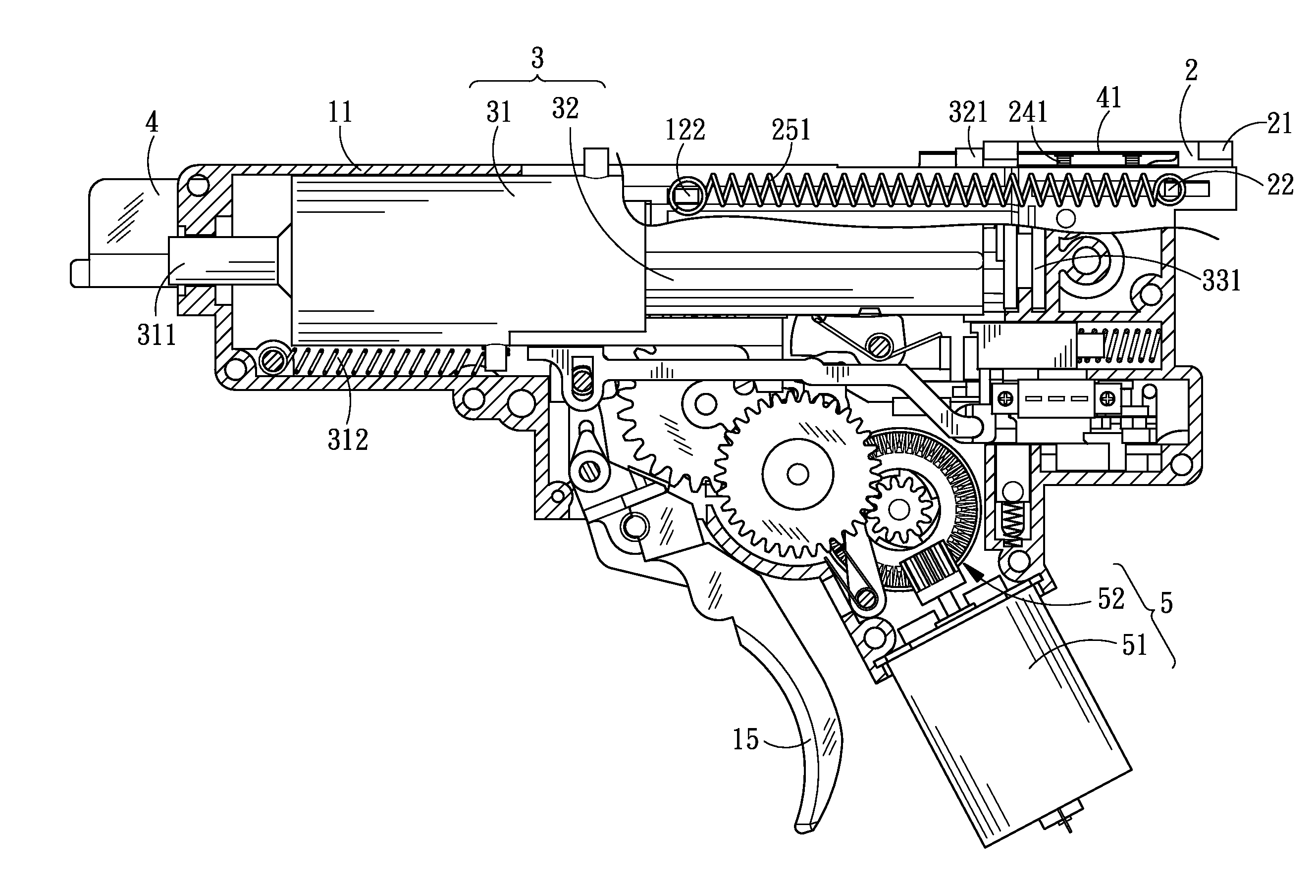
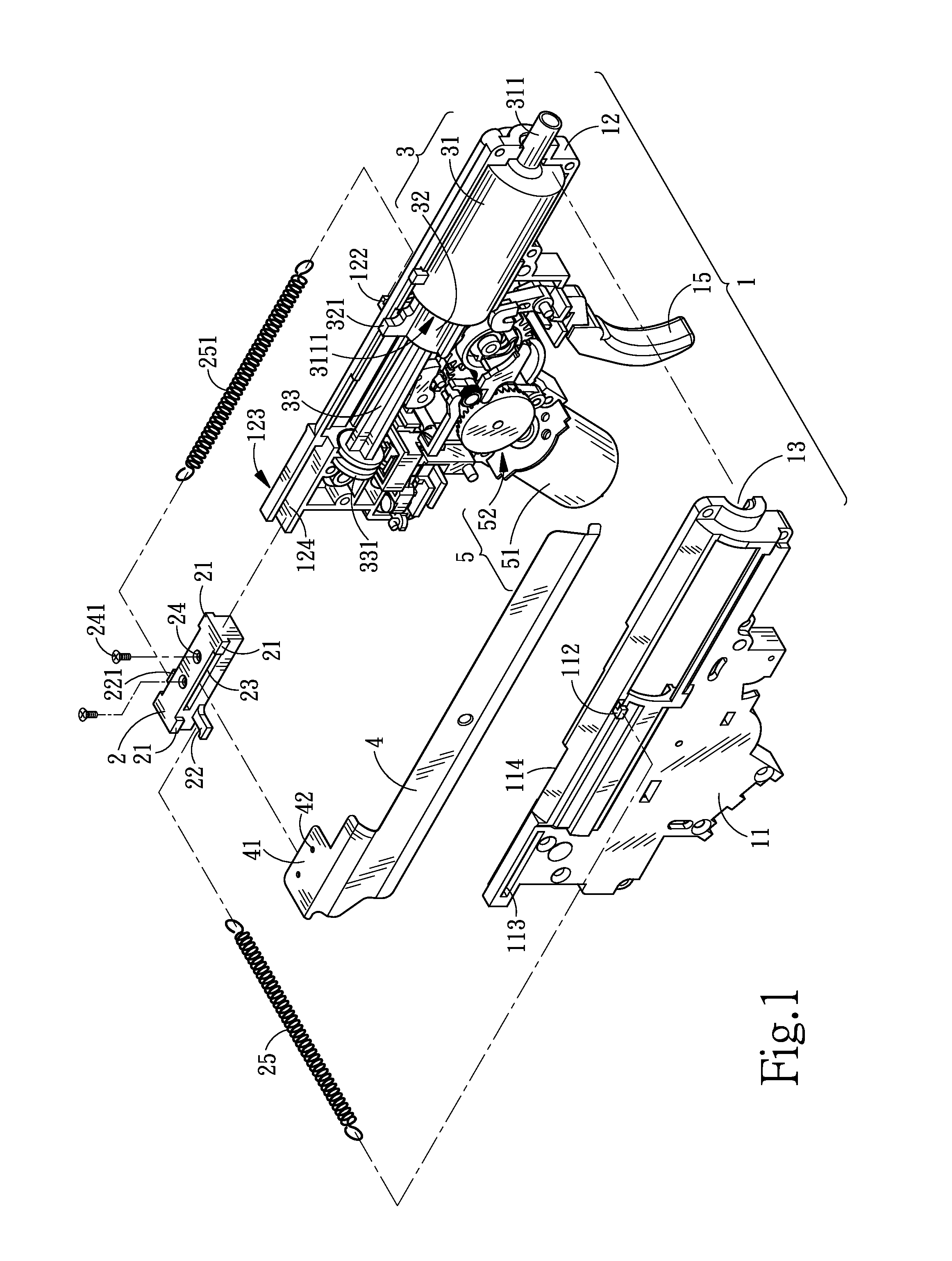
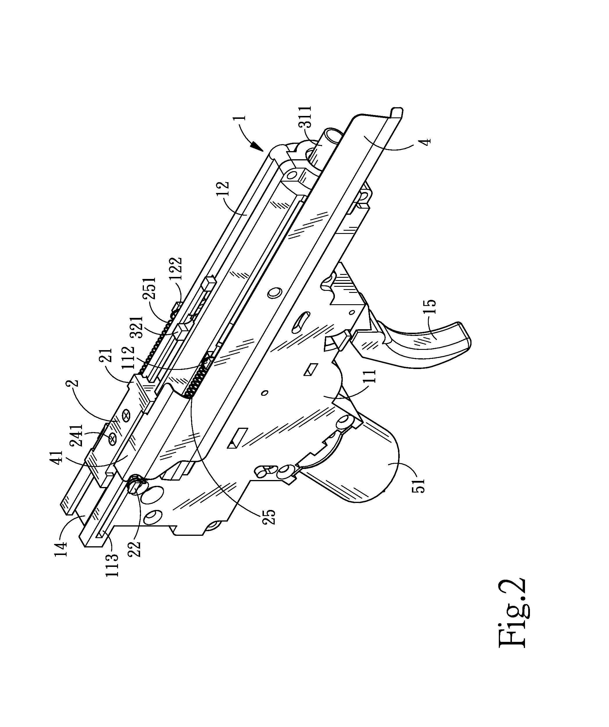
[0025]FIG. 1 is an isometric and exploded view of the related element package of the toy gun mechanism of the invention, FIG. 2 is an isometric view of the outward appearance of the overall assembled structure of the toy gun mechanism of the invention, while FIG. 3 is a front cross-sectional view of the overall assembled structure of the toy gun mechanism of the invention. As shown in FIG. 1, FIG. 2, and FIG. 3, the toy gun mechanism mainly includes an internal gun shell (1), a pull cap (2), a triggering component (3), and a shell throwing decorating plate (4). The internal gun shell (1) is combined by two opposite half gun shells (11), (12) where the two half gun shells (11), (12) have two opposite external hook parts (112), (122) furnished in the mid-section and on the external sides thereof. Side guided-channels (113), (123) are furnished respectively on the same side of the two external hook parts (112), (122). Two upper openings (114), (124) are also furnished at the top part a...


PUM


Abstract

A simulated shell-throwing action of toy gun mechanism has external hook parts furnished on the outer side of the internal gun shell, side guided-channels furnished on a side of the external hook parts, and an upper guided channel furnished at the top of the side of the side guided-channel; a pull cap being capable of sliding into the upper guided channel has a hook part capable of passing through the side guided-channel and stretching outward; a shell-throwing spring is furnished between the hook part and the external hook part of the internal gun shell; a triggering component has a gun core tube having an opening, and a piston partially stretching through the opening and into the gun core tube where the piston is capable of performing reciprocating sliding action subjected to external driving force; a stopping flange capable of contacting the stopping flange of the pull cap making the pull cap capable of performing reciprocating motion by following the piston and by coordinating the telescoping action of the shell-throwing springs is also furnished on the outer side of the piston; a shell throwing decorating plate combining at an end of the pull cap making the shell throwing decorating plate synchronously follows the pull cap to perform reciprocating action to generate the effect of simulated shell-throwing action.

Description

BACKGROUND OF THE INVENTION[0001]1. Field of the Invention[0002]The invention relates to a simulated shell-throwing action of toy gun mechanism, and more particularly, to a simulated shell-throwing action of toy gun mechanism that is applicable to small type toy gun.[0003]2. Description of the Prior Art[0004]Following the trend of various refined toy guns, more rigorous requirements are demanded on the response and action when it comes to shooting. For instance, the shell-throwing action during the actual gun-shooting is an important one in the shooting process. However, since there is no expanding gas, which is generated by the combustion of the gun powder of genuine bullet, available to be used owing to lacking of genuine bullet in the conventional toy gun structure, simulated shell-throwing action and effect during the actual gun-shooting is not easy to be achieved.[0005]In the gas toy gun structure, since a portion of the large type possesses relatively bigger cylinder (gun core...

Claims


Application Information

Patent Timeline
IPC IPC(8): F41B7/08
CPCF41B7/08F41B11/646
Inventor YANG, CHUNG-KUAN
Owner INCORN HOBBY
Learn More