
Natural alignment knee instruments

a knee and instrument technology, applied in the field of natural alignment knee instruments, can solve the problems of pain, stiffness, decreased mobility, and damage to the bones and joints, and achieve the effects of reducing mobility, pain, and stiffness

Active Publication Date: 2015-02-12
HOWMEDICA OSTEONICS CORP
View PDF0 Cites 59 Cited by
  • Summary
  • Abstract
  • Description
  • Claims
  • Application Information

AI Technical Summary

Benefits of technology

The invention provides a system for aligning a femoral bone and a tibial bone during joint replacement surgery. The system includes a femoral referencing system and a tibial resection guide that allows for adjustability of the tibial slope. The system also allows for visualization of the joint-line in a pre-arthritic or anatomic state. The invention provides a way to prepare a femoral implant that references the prepared distal femoral bone and also reference the unresected tibial surface, while maintaining the full diameter of the hole for implant preparation and using a single fixation pin placement. The system also allows for correction / refinement of the tibial cut, including tibial slope, varus alignment, valgus alignment, or any combination of those mentioned. The system includes markings to indicate the implant size for proper positioning of the guide.

Problems solved by technology

Over time and through repeated use, bones and joints can become damaged or worn.
When the cartilage wears down, fluid can accumulate in the joint areas, resulting in pain, stiffness, and decreased mobility.
A one- to two-millimeter translational misalignment, or a one- to two-degree rotational misalignment, may result in imbalanced ligaments, and may thereby significantly affect the outcome of the TKA procedure.
For example, implant misalignment may result in intolerable post-surgery pain, and also may prevent the patient from having full leg extension and stable leg flexion.
However, the conventional standards are based on static load analysis and therefore may not be able to provide an optimal joint functionality for adopting individual knee features of OA patients.

Method used


Image

  • Natural alignment knee instruments
  • Natural alignment knee instruments
  • Natural alignment knee instruments

Examples


Embodiment Construction

[0046]As used herein, the term “distal” means more distant from the heart and the term “proximal” means closest to the heart. The term “inferior” means toward the feet and the term “superior” means towards the head. The term “anterior” means towards the front part of the body or the face and the term “posterior” means towards the back of the body. The term “medial” means toward the midline of the body and the term “lateral” means away from the midline of the body.

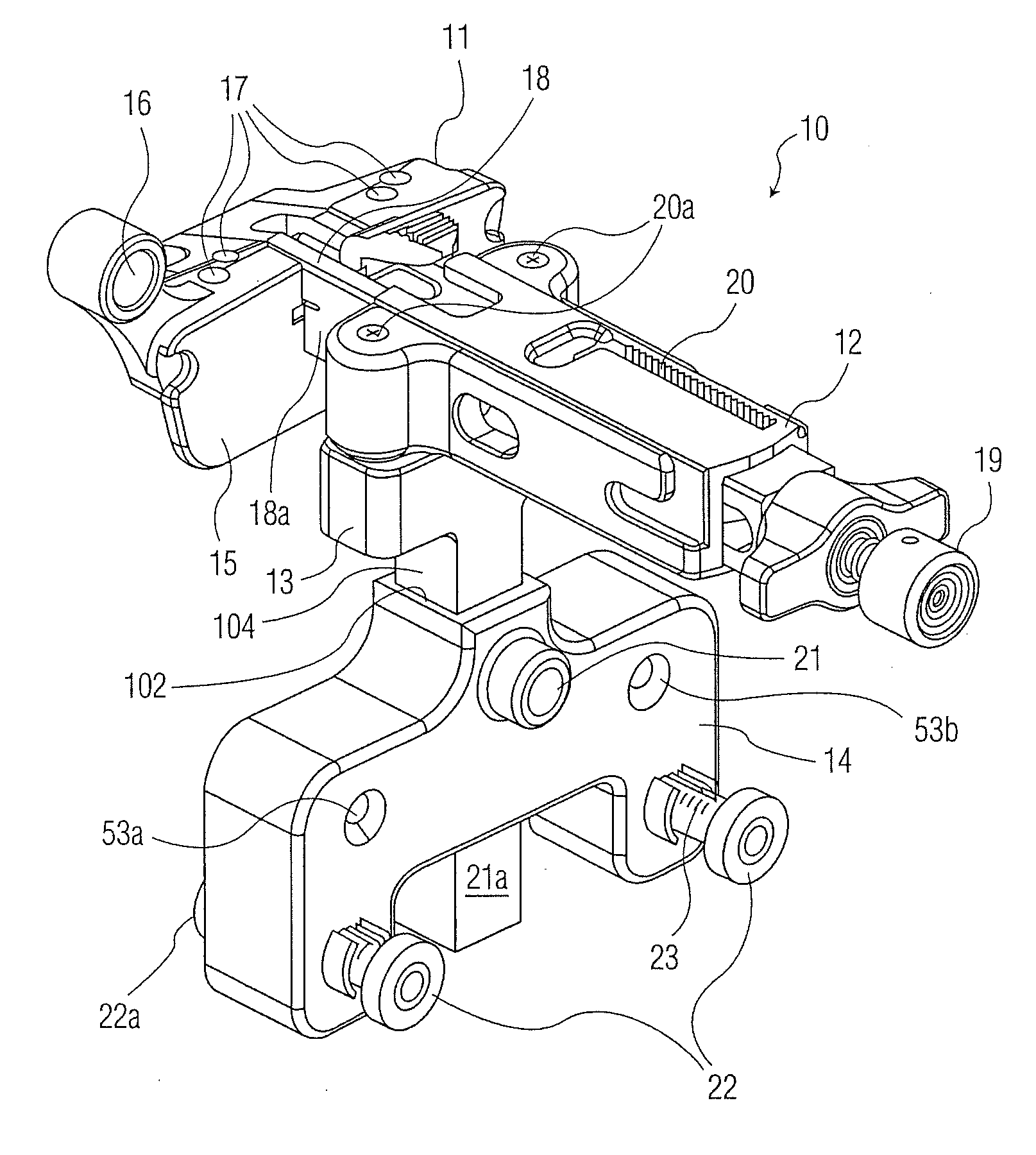
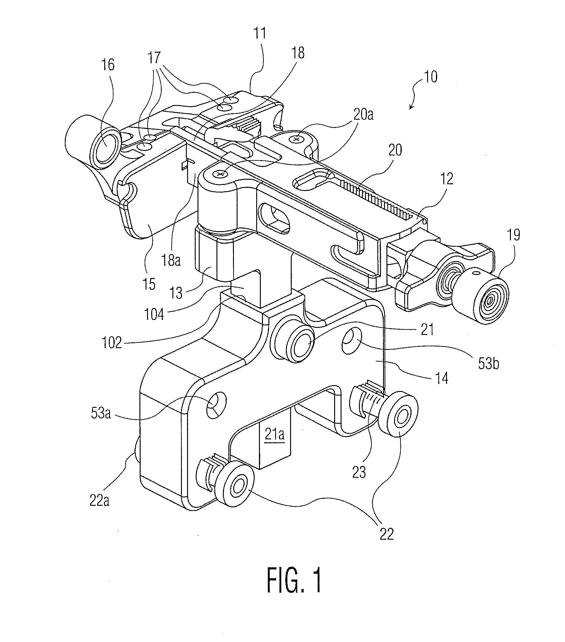
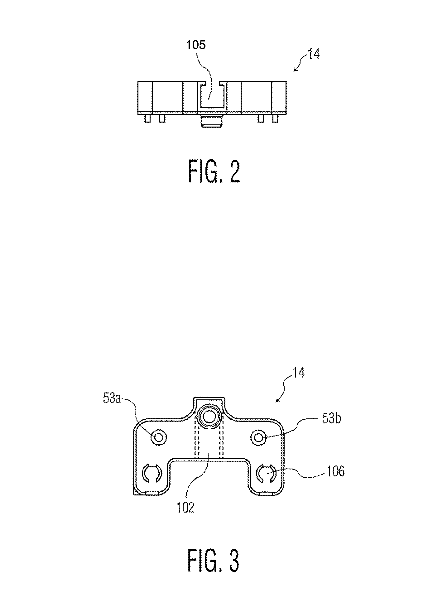
[0047]Referring to the drawings, FIG. 1 illustrates a first embodiment of an anatomic distal femoral resection guide alignment assembly generally denoted as 10 which consists of a distal femoral resection guide 11 for making a distal femur planar cut, an adjustment housing 12, an AP tower 13 moveable in an AP direction and a distal femoral referencing housing 14 having adjustable pads 22a. The distal resection guide 11 includes a cutting surface 15 for guiding a saw blade, an aperture 16 for attachment to a standard navigat...


PUM


Abstract

A method for aligning an orthopedic implant in a joint replacement includes determining the bone and cartilage deficiency from an undegenerated state caused by wear of a joint. Then a resection of a bone in the joint is made based on the deficiency of bone and cartilage from the undegenerated state and the size of a joint implant so as to locate the joint surface of the implant in the undegenerated cartilage location. The condylar wear from the undegenerated states may be assessed at a distal and posterior location on each of a medial and a lateral femoral condyle. A distal cut is made on the femur at a location adjusting for the condylar wear from the undegenerated state. The distal cut varus-valgus angle is oriented parallel to a plane across the distal femur after adjusting for wear in the distal location on the medial and lateral condyle.

Description

CROSS-REFERENCE TO RELATED APPLICATION[0001]The present application is a continuation of U.S. patent application Ser. No. 13 / 113,414, filed May 23, 2011, which claims the benefit of the filing date of U.S. Provisional Patent Application No. 61 / 347,045, filed May 21, 2010, the disclosures of which are hereby incorporated herein by reference.BACKGROUND OF THE INVENTION[0002]Over time and through repeated use, bones and joints can become damaged or worn. For example, repetitive strain on bones and joints (e.g., through athletic activity), traumatic events, and certain diseases (e.g., arthritis) can cause cartilage in joint areas, which normally provides a cushioning effect, to wear down. When the cartilage wears down, fluid can accumulate in the joint areas, resulting in pain, stiffness, and decreased mobility.[0003]Arthroplasty procedures can be used to repair damaged joints. During a typical arthroplasty procedure, an arthritic or otherwise dysfunctional joint can be remodeled or rea...

Claims


Application Information

Patent Timeline
IPC IPC(8): A61B17/17
CPCA61B17/1764A61B17/155A61B17/157A61B2017/0268A61F2/4684A61B17/15A61B17/154A61B17/56A61B2017/564A61B2017/565
Inventor AXELSON, JR., STUART L.SOLIMAN, MOHAMEDFERKO, MICHAEL C.SIMES, JR., ROBERT F.HOWELL, JAMES H.
Owner HOWMEDICA OSTEONICS CORP
Learn More