Electrical power system and method for operating an electrical power system

Inactive Publication Date: 2015-01-29
SIEMENS AG
View PDF6 Cites 6 Cited by
  • Summary
  • Abstract
  • Description
  • Claims
  • Application Information

AI Technical Summary

Benefits of technology

The present invention provides an improved and cost-effective mechanism for providing back feed power to grid connected plants. It allows plants to generate and store power for later use, reducing the need for purchasing power from the grid. This is achieved through a shared central repository of rechargeable batteries that can be used to provide electrical preheating during plant start up and to defer new peaking capacity of the electrical power system, reducing emissions. The central repository can also be installed downstream of heavily congested transmission lines to avoid congestion-related charges.

Problems solved by technology

In operation of the electrical power system, there may be situations when the individual and / or collective power output of the power plants is not enough to meet the utility power demand, or that one (or multiple) of the power plants needs to be shut down, for e.g., repair, servicing, maintenance or any other reason.
When an individual power plant shuts down, i.e., stops producing power, there may still be tasks that require power.
In the instance of a concentrated solar plant using molten salt or thermal oil, the same examples apply but there are even more serious power draws needed for pumps to keep the molten salt or oil moving or heaters needed to keep the molten salt at a temperature above its freezing point.
For plants that shut down daily, for example in peaker plants, and concentrated solar plants, the cost of purchasing this power can be significant.

Method used


Image

  • Electrical power system and method for operating an electrical power system
  • Electrical power system and method for operating an electrical power system
  • Electrical power system and method for operating an electrical power system

Examples


first embodiment

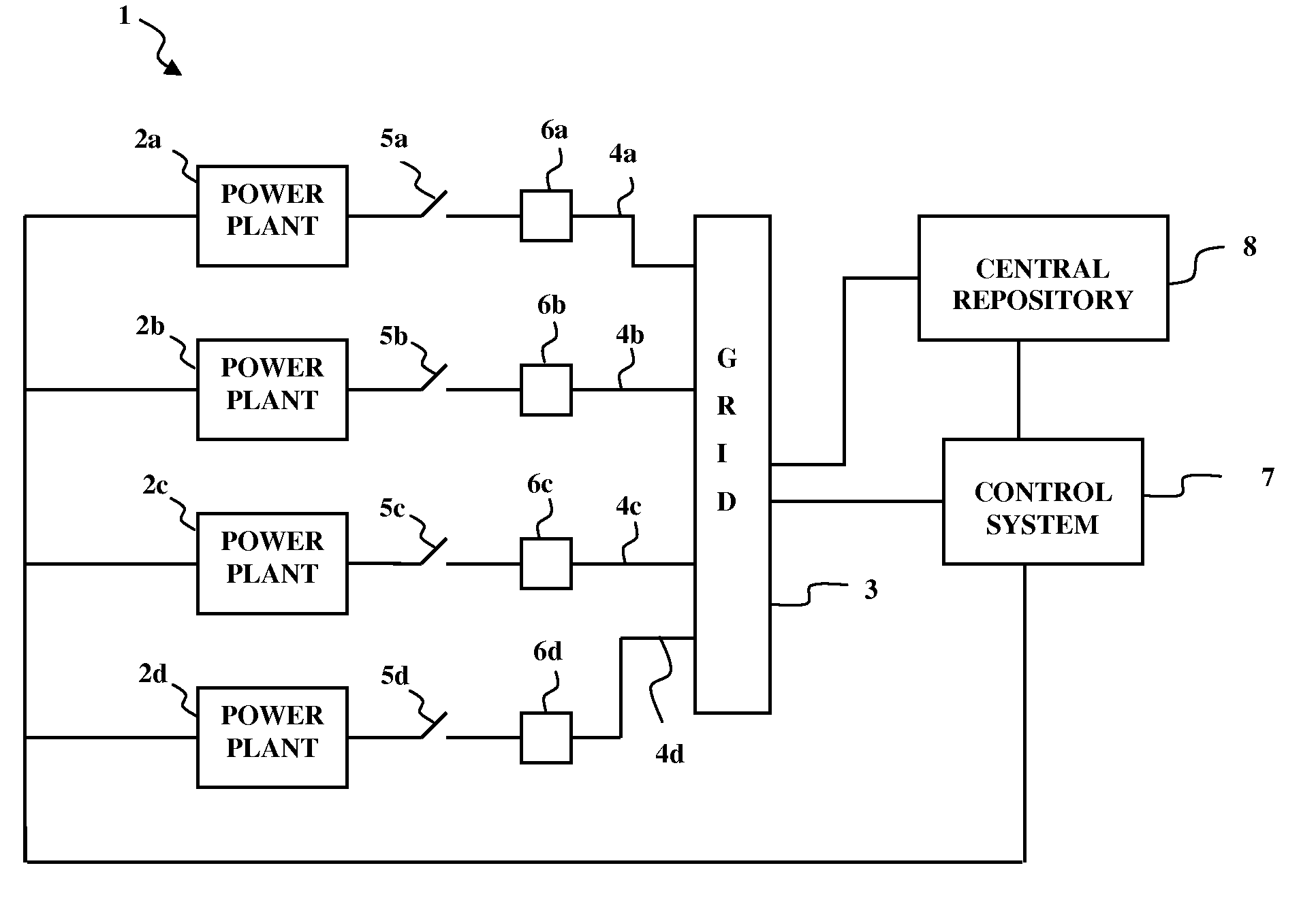
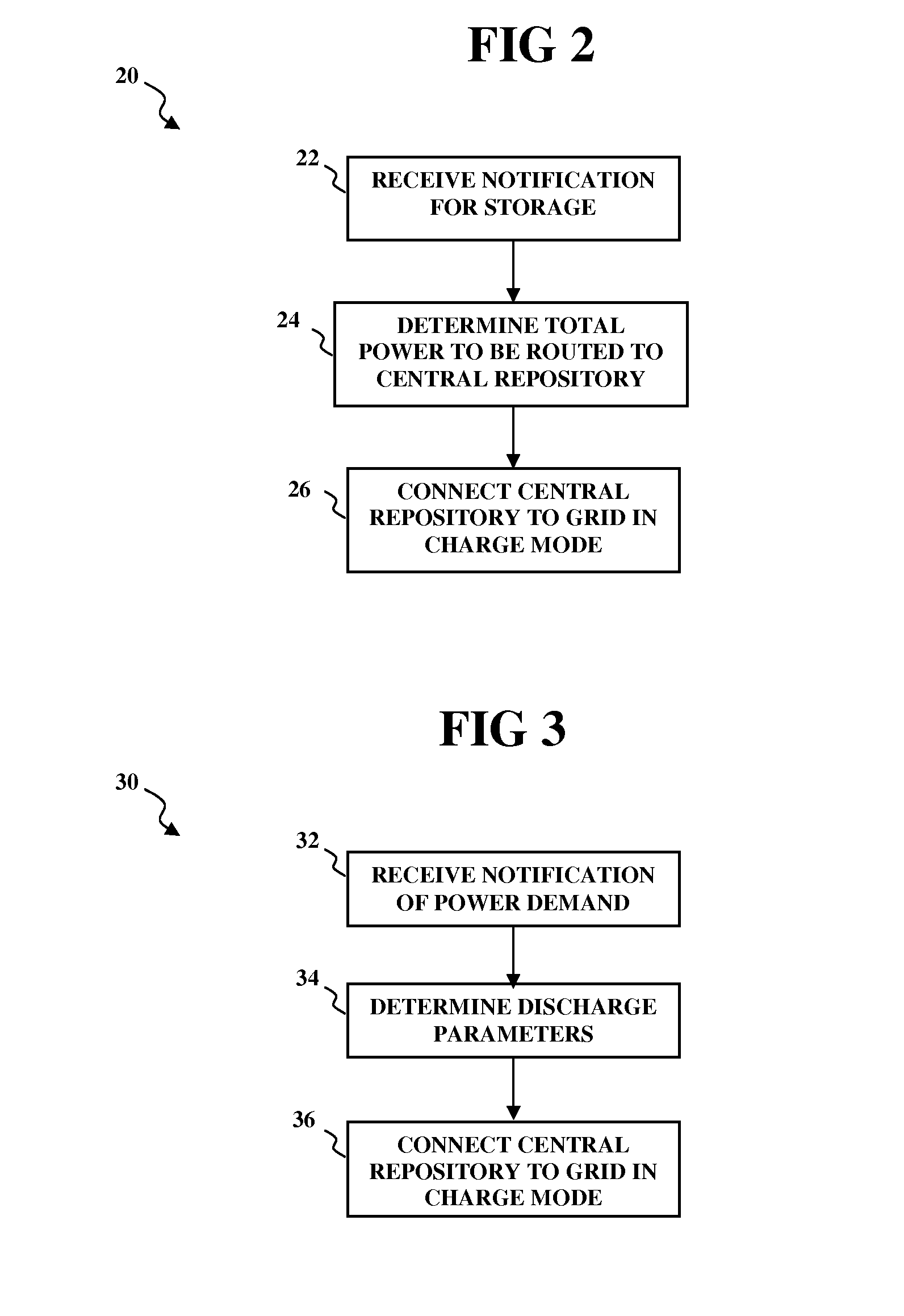
[0036]FIG. 3 is a flowchart illustrating an exemplary control method 30 for discharging power from the central repository 8 in accordance with a At step 32, the control system 7 receives a notification during a second period from an individual power plant 2a, or 2b, or 2c, or 2d which specifies a power demand by the individual power plant 2a, or 2b, or 2c, or 2d. This notification may be sent, for example, by an operator of the individual power plant 2a, or 2b, or 2c, or 2d when it goes offline or is shut down or requires power during a start up. At step 34, in response to the notification, the control system 7 determines discharge parameters, such as the exact amount of energy to be discharged from the central repository 8 and the rate of energy discharge (power). This may, for example, be specified in the notification. At step 36, the control system 7 operates to bring the repository 8 online, whereby the central repository 8 discharges the exact or nearly exact amount of power a...

second embodiment

[0042]FIG. 4 is a flow chart illustrating a control method 40 for discharging the central repository 8 according to a The method may be implemented by the control system 7. The method 40 involves continuously monitoring a grid requirement (step 42), which may, for example be, in terms of power and / or voltage, among other parameters. At step 44, a change in grid requirement or a new grid requirement or peak demand is detected. At step 46, determination is made as to whether the central repository 8 is required to be brought online (in discharge mode). If so, at step 48, a determination is made on the discharge parameters of the central repository 8, for example, in terms of voltage and / or power. At step 49, the central repository 8 is brought online to discharge power to the grid 3 in a controlled manner on the basis of the determined discharge parameters. The central repository 8 may be subsequently taken offline (step 48a) if the grid requirement changes.

[0043]The above method all...


PUM


Abstract

An electrical power system includes a power grid and a plurality of power plants connected to the power grid. A central repository including one or more electrical energy storage devices is connected directly to the power grid. The one or more energy storage devices are configured to be connected to the power plants via the power grid. The central repository is operable to draw a portion of a power output produced by one or more of the power plants via the power grid during a first period, for storage therein. The central repository is operable to discharge power to the power grid during a second period shifted in time from the first period. The discharged power is a function of a grid requirement or a function of a power demand notified by an individual power plant of the electrical system.

Description

FIELD OF INVENTION[0001]The present invention relates to an electrical power system, particularly to a system and method for power storage in relation to grid connected power plants.BACKGROUND OF INVENTION[0002]An electrical power system typically includes one or more power plants supplying power to a grid. The power plants may include, for example, conventional fossil-fired power plants such as gas or steam turbine power plants, and / or renewable power plants such as wind turbines, photovoltaic cells, and concentrated solar plants, among others. The grid transmits power to a utility via a distribution network.[0003]In operation of the electrical power system, there may be situations when the individual and / or collective power output of the power plants is not enough to meet the utility power demand, or that one (or multiple) of the power plants needs to be shut down, for e.g., repair, servicing, maintenance or any other reason. For example, certain power plants, referred to as peake...

Claims


Application Information

Patent Timeline
IPC IPC(8): H02J15/00H02J4/00
CPCH02J4/00H02J15/00H02J3/28H02J3/30H02J3/32H02J3/38Y02E60/16H02J2300/28H02J2300/20H02J2300/24H02J3/381Y02E10/56Y02E10/76H02J3/466Y02E70/30
Inventor SCHEURLEN, MICHAELSHARP, JAMES H.HANSEL, MONICA B.BRIESCH, MICHAEL S.
Owner SIEMENS AG
Why Eureka
Try Eureka