Wind turbine nacelle

a wind turbine and nacelle technology, applied in the field of wind turbine nacelles, can solve the problems of occupying a large space in the pod of the generator, affecting the operation of the generator, so as to avoid too many individual parts, reduce costs, and avoid complicated and expensive fittings

Active Publication Date: 2015-01-15
WOBBEN PROPERTIES GMBH
View PDF37 Cites 22 Cited by
  • Summary
  • Abstract
  • Description
  • Claims
  • Application Information

AI Technical Summary

Benefits of technology

[0033]In that way it is possible inter alia to provide that as few components as possible and a weight which is correspondingly as low as possible is required, which in turn can lead to a reduction in costs. It is possible to avoid too many individual parts, an additional casing which is complicated and expensive to fit, and unnecessary material expenditure, due to a disadvantageous flow of force in the drive train. Instead, a simplification in assembly, a reduction in the individual parts on the building site and an application of force which is as direct as possible from the rotor blade to the generator can be achieved or can thereby be at least sought to be achieved. In addition any additional pod hood can also become superfluous if the blade connecting region also structurally encloses the generator in such a way that the generator is thereby adequately encapsulated and protected from the influences of weather.

Problems solved by technology

In the case of a gearless wind power installation the generator also takes up some space.
By virtue of its size, depending on the respective kind and size of the wind power installation, such a machine carrier can take up considerable space in the pod, in which case comparatively little space remains around the machine carrier.

Method used


Image

  • Wind turbine nacelle
  • Wind turbine nacelle
  • Wind turbine nacelle

Examples


Embodiment Construction

[0056]Hereinafter identical references can denote similar but non-identical components. In addition the same components can be shown on different scales.

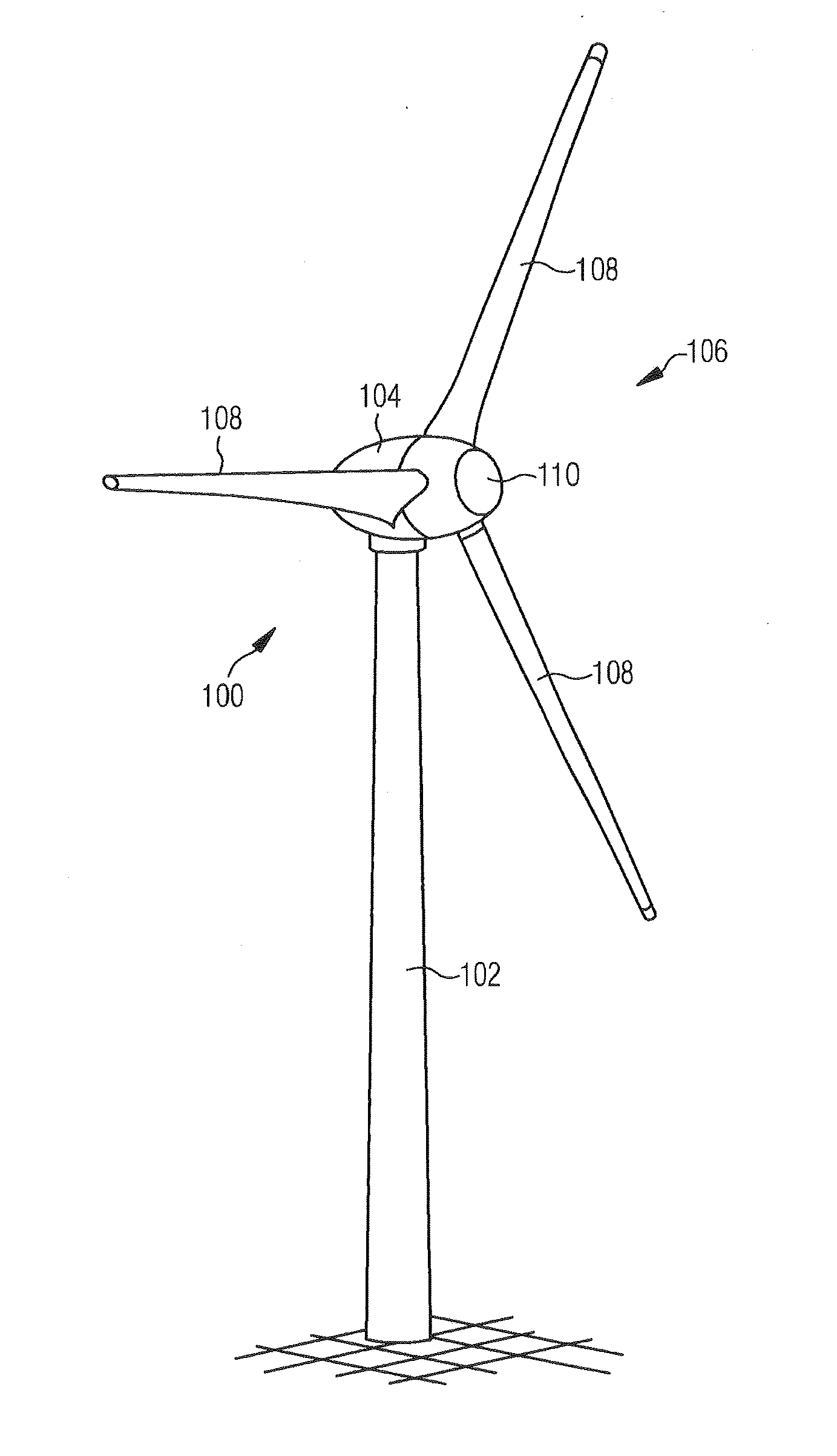
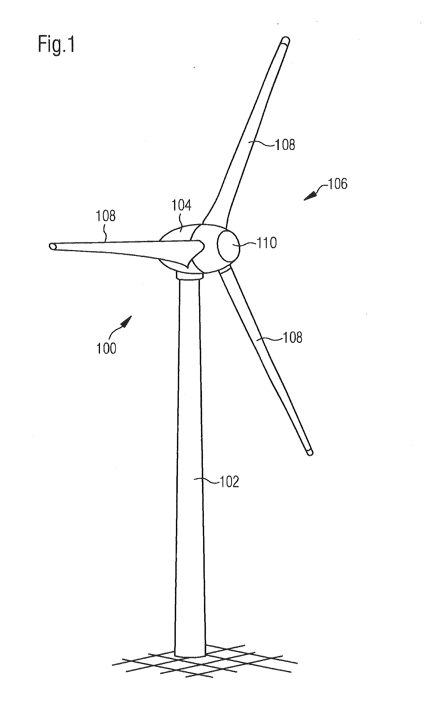
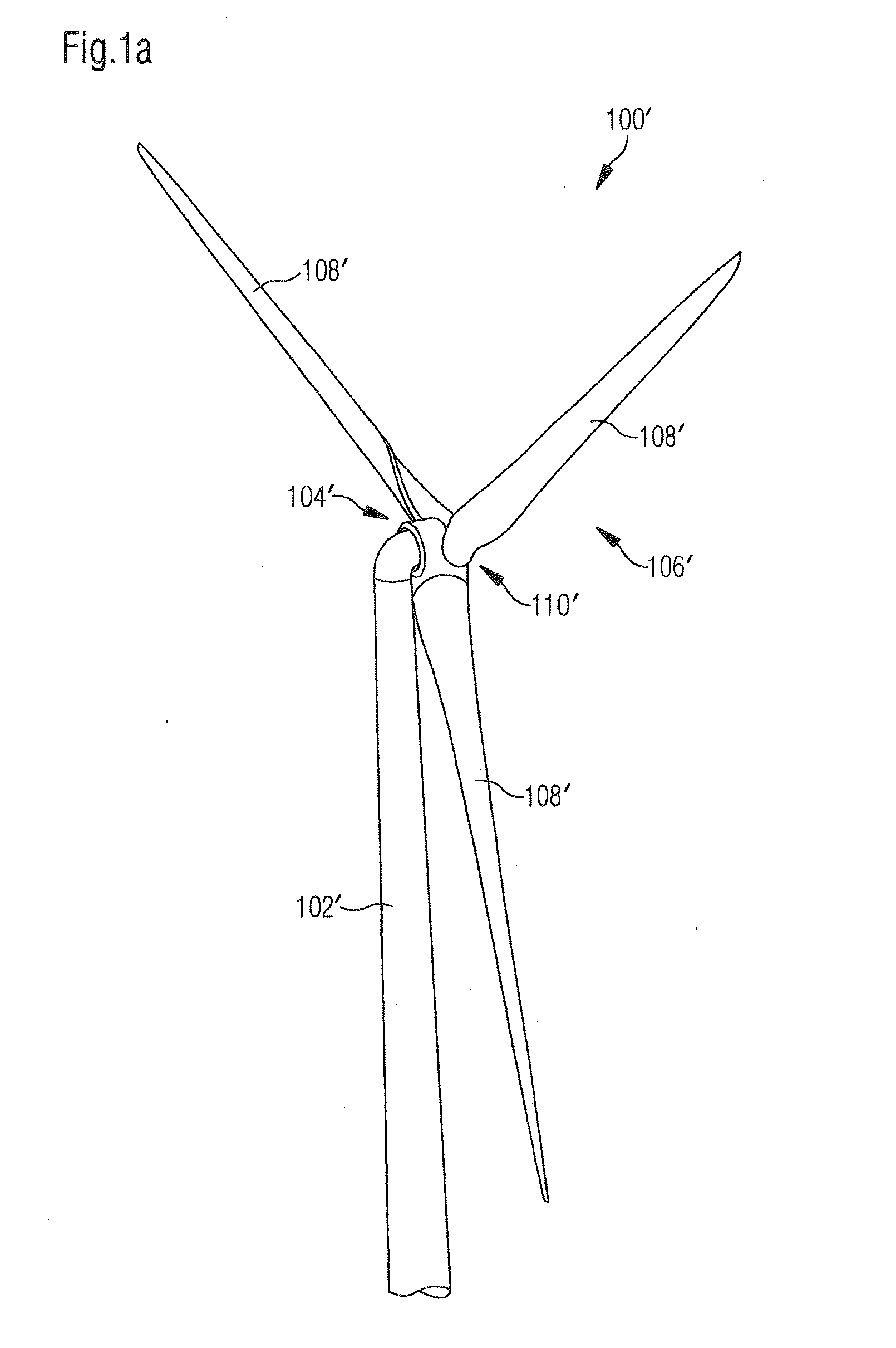
[0057]FIGS. 1 and 1a each show a wind power installation 100, 100′ having a pylon 102, 102′ and a pod 104, 104′. Arranged on the pod 104, 104′ is a rotor 106, 106′ with three rotor blades 108, 108′ and a spinner 110, 110′. The rotor 106, 106′ is caused to rotate in operation by the wind and thereby drives a generator in the pod 104, 104′.

[0058]The pod 1 in FIG. 2 has a stationary part 2 and a rotating part 4. The stationary part 2 extends far into the rotating part 4. The stationary part 2 is fixed by way of an azimuth flange 6 to an azimuth bearing 8 which in turn is fixed to a pylon flange 10 of a pylon 12. Of the pylon 12, only its upper region, namely its pylon head 26 with a working platform 14 is shown.

[0059]Azimuth drives 16 are arranged in the pylon 12 in the proximity of the pylon flange 10 and in the proximity of the azimu...


PUM

PropertyMeasurementUnit
power outputaaaaaaaaaa
air gap diameteraaaaaaaaaa

Abstract

The invention relates to nacelle of a wind turbine. According to the invention, the wind turbine has a tower or mast, an aerodynamic rotor, and a generator having an electric-machine rotor and a stator, and the nacelle is provided with a nacelle covering, wherein the nacelle, in particular the nacelle covering is self-supporting.

Description

BACKGROUND[0001]1. Technical Field[0002]The present invention concerns a pod of a wind power installation.[0003]2. Description of the Related Art[0004]Wind power installations are generally known. In a typical wind power installation as shown in FIG. 1 an aerodynamic rotor (106) is rotated by the wind and thereby generates electric energy by means of a generator. Such a generator and further components required for operation of the wind power installation are disposed in a pod. The further components can include for example an installation control system such as azimuth drives and the actuating system thereof, possibly a rectifier or frequency converter and the actuating system thereof, and heating or cooling means and the actuating system thereof, to give just some examples. In that case the electric devices are predominantly disposed in suitable switch cabinets arranged in the pod. In addition walkway and standing regions are to be provided so that service personnel can enter the ...

Claims


Application Information

Patent Timeline
Patent Type & Authority Applications(United States)
IPC IPC(8): F03D11/04F03D9/00
CPCY10T29/4932F03D9/002F03D11/04F03D1/0691F05B2240/14F05B2240/50F03D9/25F03D13/10F03D13/20F03D15/20F03D80/00F03D80/50F03D80/70F03D80/80Y02E10/72Y02E10/728
Inventor ROER, JOCHENSARTORIUS, FLORIAN
Owner WOBBEN PROPERTIES GMBH
Why Eureka
Try Eureka