Pattern matching method and pattern matching apparatus

a matching method and pattern technology, applied in the field of matching methods and matching apparatuses, can solve problems such as narrowing down the edge extraction domain and the inapplicability of methods

Active Publication Date: 2015-01-15
CANON KK
View PDF1 Cites 12 Cited by
  • Summary
  • Abstract
  • Description
  • Claims
  • Application Information

AI Technical Summary

Benefits of technology

[0009]According to an aspect of the present invention, there is provided a pattern matching method of detecting an image of a detection target from a search image obtained by imaging the detection target by performing pattern matching between the search edge image and a model edge image concerning the detection target, comprising: obtaining a reference image of the detection target; generating the model edge image on a basis of the reference image; generating the edge extraction domain that is specified as a portion where the model edge image can exist by overlying a plurality of the model edge images obtained with at least one of (i) a rotation process of rotating the model edge image within a predetermined range around a rotation center of the model edge image, (ii) an enlargement / reduction process of enlarging / reducing the model edge image within a predetermined range around the rotation center, and (iii) a translation process of translating the model edge image within a predetermined range; and performing pattern matching between the model edge image and the search edge image generated by performing edge extraction process for the edge extraction domain in the search image.

Problems solved by technology

This makes the method inapplicable to a detection target having no corner such as a circle.
Also, if a corner-like shape which is not a detection target exists in the background of the detection target, the method detects the corner other than the detection target, and hence cannot narrow down the edge extraction domain.

Method used


Image

  • Pattern matching method and pattern matching apparatus
  • Pattern matching method and pattern matching apparatus
  • Pattern matching method and pattern matching apparatus

Examples


first embodiment

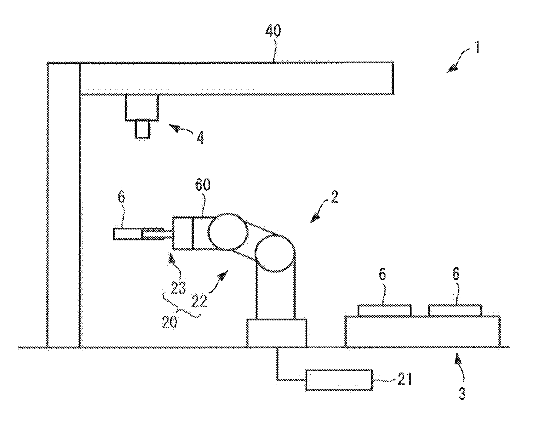
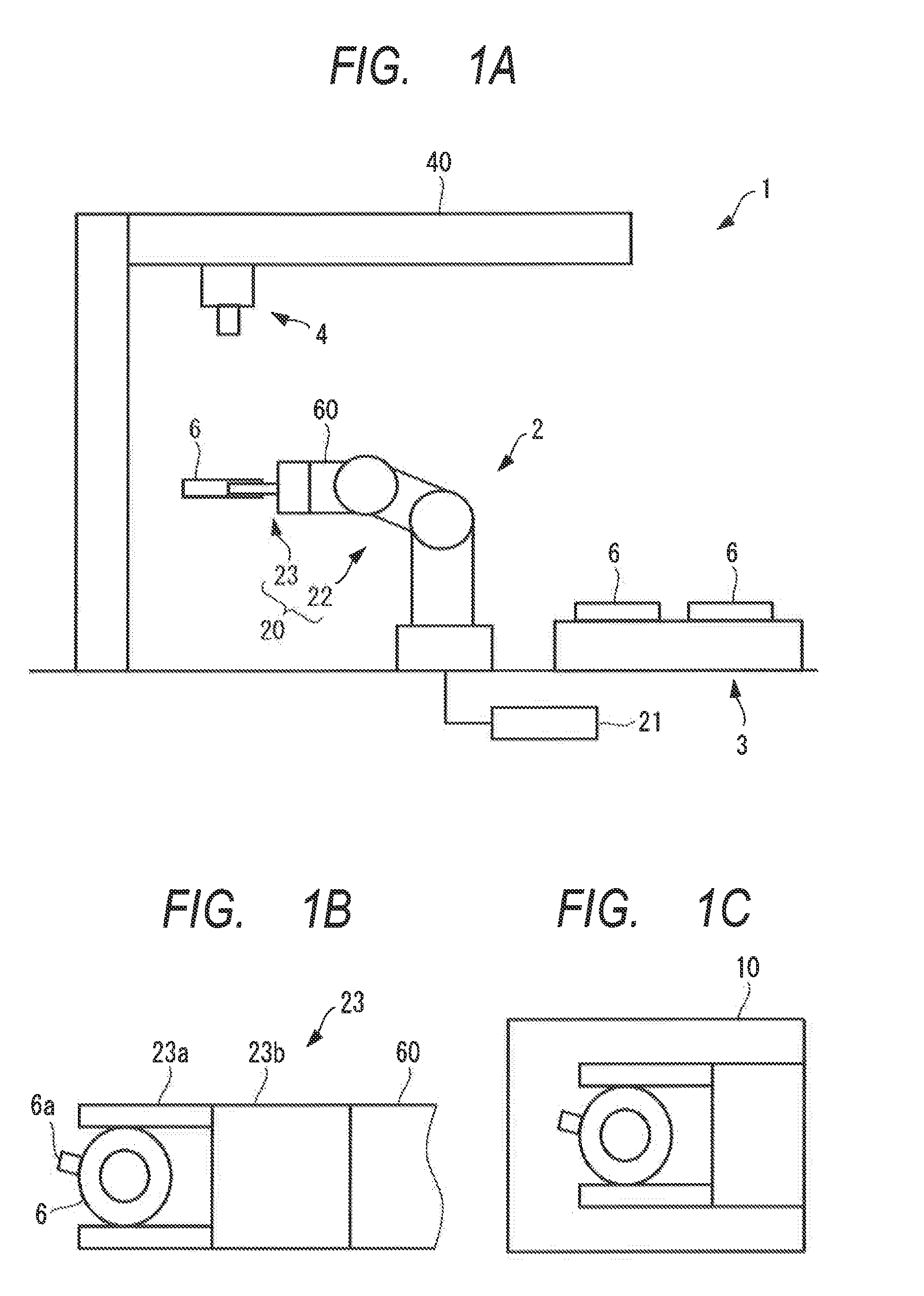
[0023]As shown in FIGS. 1A to 1C, a robot system 1 includes a robot apparatus 2, a work supply apparatus 3 for supplying works 6 to the robot apparatus 2, a camera 4, and a control apparatus 21 for controlling the robot apparatus 2 and the camera 4.

[0024]The robot apparatus 2 can process the work (detection target) 6, and includes a robot main body 20, and the control apparatus 21 controls the robot main body 20 and camera 4. As an example of the work 6, the work 6 in FIGS. 1A to 1C has an annular shape, and partially includes a projection 6a which projects outward in the radial direction so as to function as a phase reference part. Although the projection 6a is the phase reference part of the work 6, the present invention is not limited to this, and the phase reference part may also be, e.g., a mark. The camera 4 is fixed on a camera fixing base 40, and capable of sensing, from above, an image of the work 6 supplied to the robot apparatus 2 by the work supply apparatus 3, i.e., the...

second embodiment

[0061]Next, a robot system 1 according to the second embodiment will be explained.

[0062]In the second embodiment, a model edge image 12 is formed based on three-dimensional shape data 106 of CAD as design data of a work 6 as shown in FIGS. 9A and 9B, when compared to the first embodiment. Also, when forming an edge extraction domain 13 in the second embodiment, a shape sum domain is formed for an enlargement / reduction range in addition to a rotation range and translation range, when compared to the first embodiment. That is, the second embodiment takes account of a case in which the distance between the work 6 and a camera 4 changes accordingly and the size of the work 6 in a search edge image 11 changes in an actual search process.

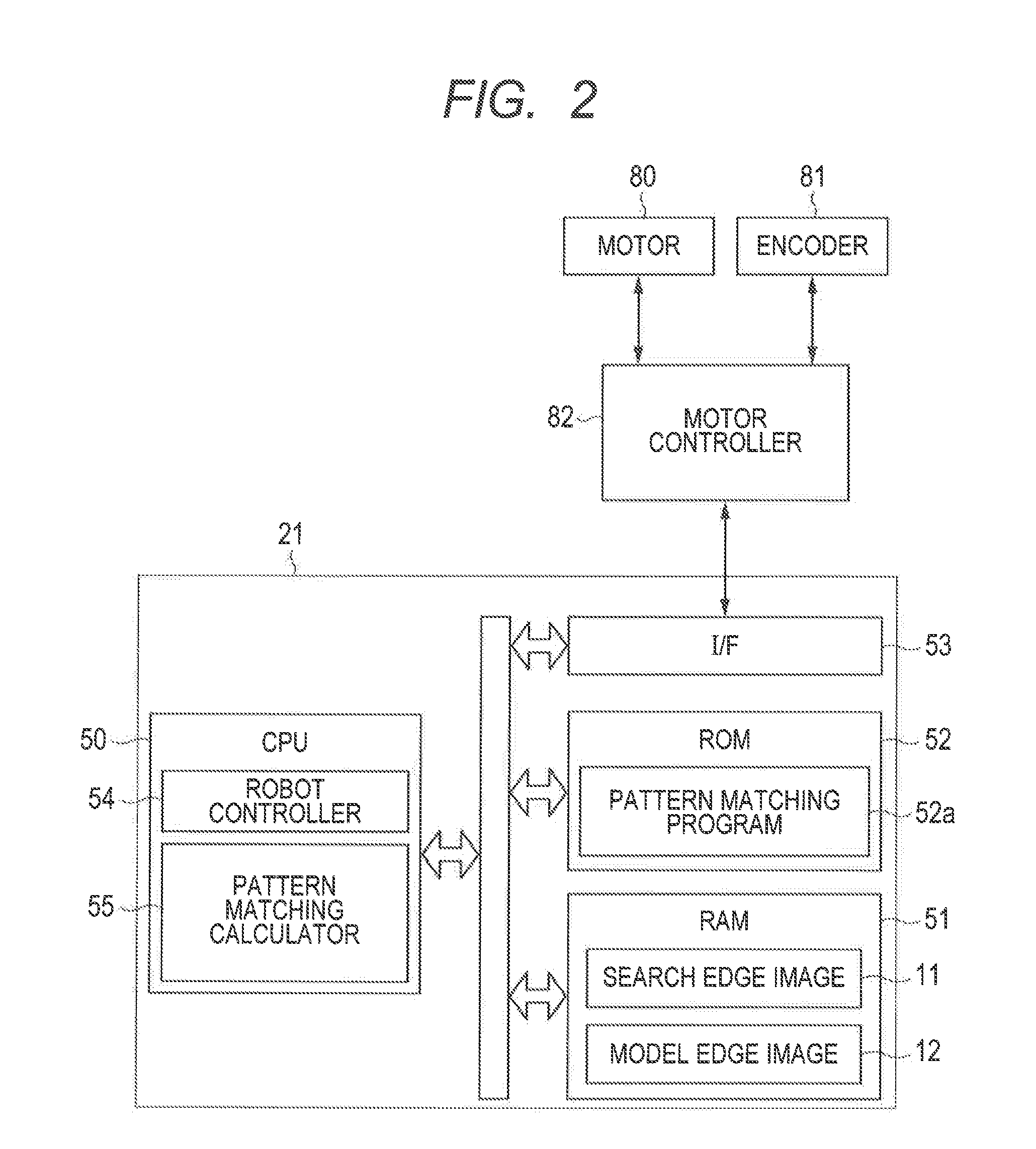
[0063]The difference of this embodiment from the first embodiment is processing in a pattern matching calculator 55. Since, however, the hardware configuration is the same as that of the first embodiment, the same reference numerals denote the same parts,...


PUM


Abstract

According to an aspect of the present invention, there is provided a pattern matching method of detecting an image of a detection target from a search image, comprising: obtaining a reference image of the detection target; generating the model edge image on a basis of the reference image; generating the edge extraction domain that is specified as a portion where the model edge image can exist by overlying a plurality of the model edge images obtained with at least one of rotating the model edge image within a predetermined range around a rotation center of the model edge image and translating the model edge image within a predetermined range; and performing pattern matching between the model edge image and the search edge image.

Description

BACKGROUND OF THE INVENTION[0001]1. Field of the Invention[0002]The present invention relates to a pattern matching method and pattern matching apparatus for performing pattern matching between a search edge image generated based on a search image, and a model edge image generated based on a detection target.[0003]2. Description of the Related Art[0004]In the field of image processing, pattern matching methods are conventionally well known as methods of detecting the position of, e.g., a work as a detection target. Of these methods, shape pattern matching (to be referred to as pattern matching hereinafter) has widely spread because it is a method which is strong against an illumination change and the hiding and missing of an object and has a high robustness.[0005]In the pattern matching, the similarity is calculated by using the shape features of a model (reference image) and search image, so it is necessary to extract the shape features of the images. As a method of extracting the ...

Claims


Application Information

Patent Timeline
Patent Type & Authority Applications(United States)
IPC IPC(8): G06K9/46
CPCG06K9/4638G06V10/7515
Inventor KITAJIMA, HIROSHI
Owner CANON KK
Why Eureka
Try Eureka