Video encoding and decoding with prediction at higher precision

a video encoding and prediction technology, applied in the field of video compression and decompression systems, can solve the problems of loss information that cannot be recovered at the decoder, introduce some quality degradation, increase the precision of storing resources, etc., and achieve the effect of improving the coding efficiency of video coding, high accuracy, and better prediction accuracy

Active Publication Date: 2015-01-15
BRITISH BROADCASTING CORP
View PDF5 Cites 18 Cited by
  • Summary
  • Abstract
  • Description
  • Claims
  • Application Information

AI Technical Summary

Benefits of technology

[0003]This invention aims at improving coding efficiency in video coding by using high accuracy sample values during prediction. While a video decoder provides reconstructed samples with values that cover specific range, for example 0 to 2B, it would be useful if some modules of the prediction can use a higher range, for example 0 to 2B+BI with BI>0, in order to benefit from better precision of the predictors as well as of the entropy decoded samples.
[0004]Typically video decoder reconstructs samples from an image block and in agreed accuracy stores them in frame buffers to be used for further processing (e.g. in-loop filters), prediction (intra or inter) and finally for display. However, the compression can be improved when increased accuracy of samples (higher range of values) is used. While it is typically expensive to store reconstructed samples in higher accuracy this invention introduces a concept where the prediction operates in higher accuracy, compared to the accuracy of reconstructed samples from frame buffers.
[0005]This invention increases the precision of the predictor applied to differential samples, i.e. the samples obtained after subtraction of the signal x with the predictor p, d=x−p. It will be understand by the embodiments of this invention that the signal x can be both original video signal s or a different representation obtained starting from s. One example of differential signal d is given by subtracting s with a predictor p. In this invention this differential samples will be denoted as residuals. Another example of differential samples is given by the subtraction of the residual d with another predictor p′. In this invention this differential samples will be denoted as differential residuals.
[0014]The precision of the result of the addition of the predictor and the differential samples in higher accuracy may be reduced by clipping to a precision that is higher than the precision of the reconstructed samples.
[0015]In another aspect, the present invention consists in a method of video encoding an input image in a processor, in which a locally decoded image is formed to avoid drift between an encoder and a remote decoder, the method comprising the steps of forming a predictor from reconstructed data with higher precision than the precision of the input image; subtracting the obtained predictor at the matching accuracy from the input image to obtain differential samples for use in forming the encoded output; performing down-scaling of the differential samples for use in forming a locally decoded image at the same precision as said input image. The predictor may be subtracted from the input image so that the differential samples are residual samples or the predictor may be subtracted from residual samples so that the differential samples are differential residual samples. Reconstructed residual samples may be kept in higher precision for reconstruction of other residual samples in the block.

Problems solved by technology

The lost information cannot be recovered at the decoder and this loss may introduce some quality degradation (artefacts).
However, this increased precision requires more storing resources to keep reconstructed data for future prediction.

Method used


Image

  • Video encoding and decoding with prediction at higher precision
  • Video encoding and decoding with prediction at higher precision
  • Video encoding and decoding with prediction at higher precision

Examples


Embodiment Construction

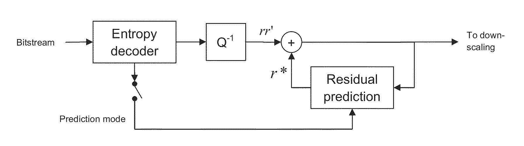
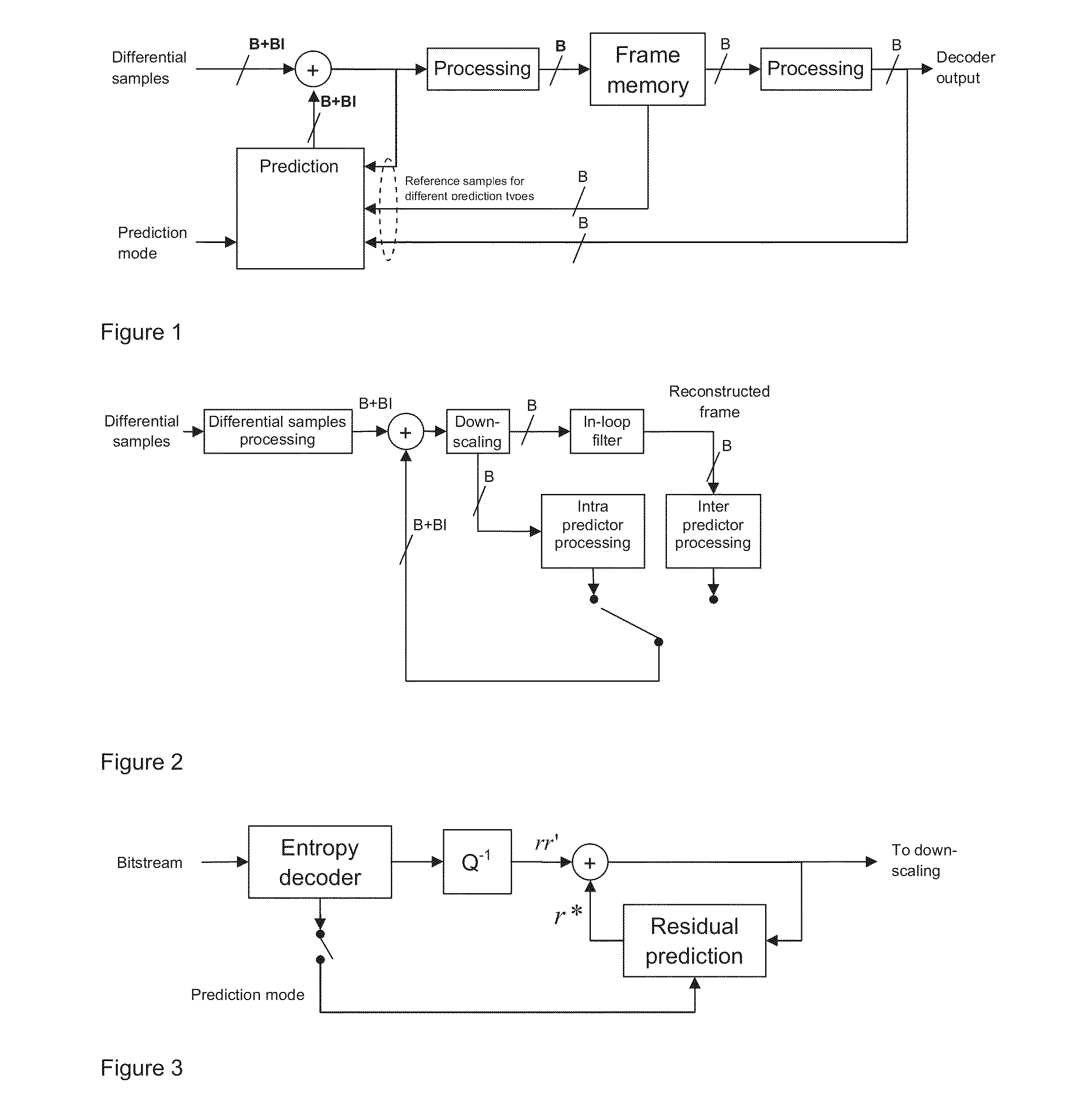
[0037]The present invention is now described in detail starting with the general framework which performs reconstruction from differential samples using a predictor in higher accuracy (see FIG. 1). Then the invention is detailed in several specific instances derived from this general framework. There is disclosed herein a method for reconstructing video pixels from differential samples using a predictor with higher precision (accuracy) values.

[0038]Accordingly, the residual samples are reconstructed by adding a predictor with precision equal to B+BI. The obtained samples are stored in the frame memory at precision equal to B and made available for reconstruction of future video pixels. The processing operated over the frames stored in memory will be still carried out with precision equal to B and the up-scaling to increased precision B+BI will be performed in the prediction module as illustrated in FIG. 1. It should be noted that typical addition and subtraction operations increase ...


PUM


Abstract

A video decoder has a transform mode and a transform skip mode and in the transform skip mode a residual prediction mode is selected. A compressed bit-stream is entropy-decoded to obtain a block of quantised values. An inverse quantiser operates in the transform mode to form transform coefficients and in the transform skip mode to form differential residual values. In the transform mode an inverse transform is performed to form residual values. In the transform skip mode residual prediction is used perform residual prediction using high accuracy locally decoded residual value. The residual value is then down-scaled to obtain the reconstructed residual. A block predictor is formed from decoded image values at the same precision at which video samples are stored in the frame memory.

Description

FIELD OF THE INVENTION[0001]This invention is related to video compression and decompression systems, notably to a method which allows improvement of the compression efficiency of video coding by performing prediction of samples in high precision.BACKGROUND TO THE INVENTION[0002]This invention is directed to the video compression area which aims at reducing the bit-rate required to transmit and store a video content while maintaining at the same time an acceptable visual quality (lossy coding). Data compression in lossy video coding is achieved by discarding some redundant information in the source data. The lost information cannot be recovered at the decoder and this loss may introduce some quality degradation (artefacts). To limit the annoyance of artefacts, the information to be discarded should be carefully selected by efficiently exploiting the redundancy among video data. Lossy video coding techniques as those standardised by the H.264 / AVC and H.265 / HEVC standards aim at reduc...

Claims


Application Information

Patent Timeline
Patent Type & Authority Applications(United States)
IPC IPC(8): H04N19/593
CPCH04N19/00763H04N19/124H04N19/12H04N19/176H04N19/61
Inventor NACCARI, MATTEOMRAK, MARTA
Owner BRITISH BROADCASTING CORP
Why Eureka
Try Eureka