
Method and device for controlling the dynamic confinement of an enclosure

a dynamic confinement and enclosure technology, applied in the direction of liquid/fluent solid measurement, volume/mass flow by differential pressure, structural/machine measurement, etc., can solve the problems of significant extension of deadlines, drop in extraction flow rate, additional costs, etc., to ensure the quality of confinement, avoid any risk of contamination outside the enclosure, and ensure the effect of quality confinemen

Inactive Publication Date: 2015-01-15
COMMISSARIAT A LENERGIE ATOMIQUE ET AUX ENERGIES ALTERNATIVES
View PDF0 Cites 2 Cited by
  • Summary
  • Abstract
  • Description
  • Claims
  • Application Information

AI Technical Summary

Benefits of technology

The patent text is about a method to monitor the confinement of an enclosure when it is at a reduced pressure or a raised pressure compared to the exterior surroundings. This method guarantees the quality of confinement and prevents any risk of contamination outside the enclosure during cleanup or dismantling operations. The method also reduces the cost of carrying out the work and eliminates the constraints associated with creating a reduced pressure or placing the enclosure at a raised pressure.

Problems solved by technology

This reduced pressure is currently measured at the start of each working shift, but it is not possible from this to deduce with certainty that this level of reduced pressure is being maintained throughout the cleanup operations and / or the operations of dismantling contaminated material.
Specifically, this reduced pressure may, for example, vary suddenly as a result of a break in the static confinement or alternatively as a result of the filtration system becoming plugged, leading to a drop in the extraction flow rate.
Now, such work stoppages lead to additional costs and significant extensions of deadlines which are incompatible with the economic requirements of the companies involved.

Method used


Image

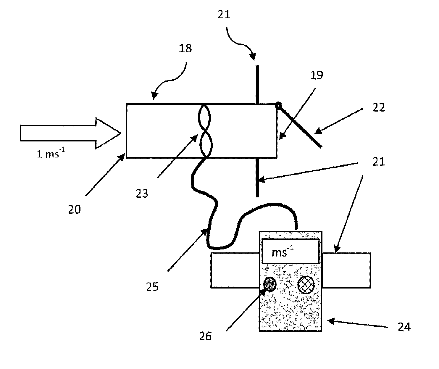
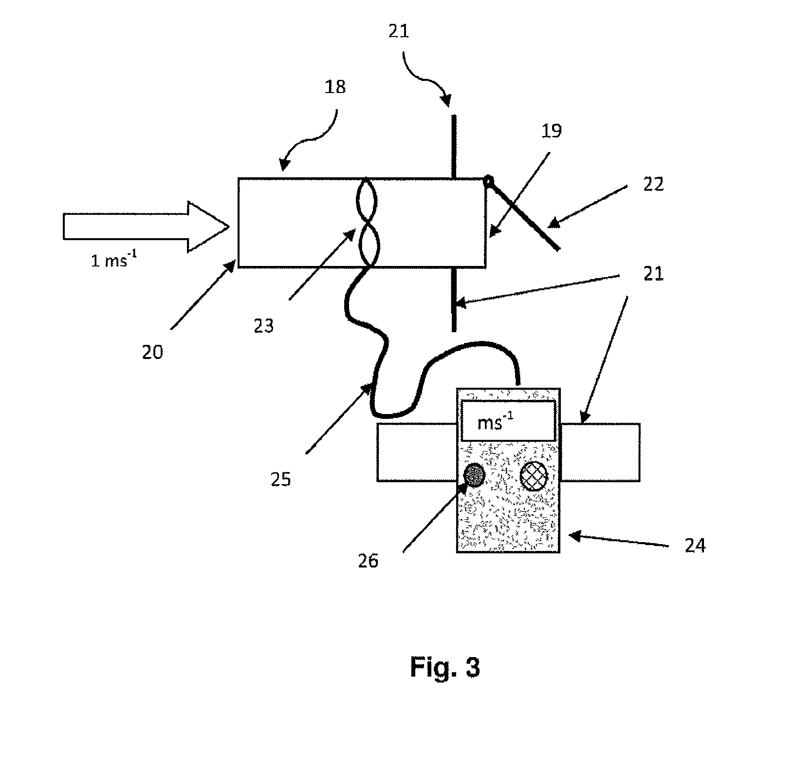
  • Method and device for controlling the dynamic confinement of an enclosure
  • Method and device for controlling the dynamic confinement of an enclosure
  • Method and device for controlling the dynamic confinement of an enclosure

Examples


Embodiment Construction

[0079]First of all, it should be noted that the figures are not to scale.

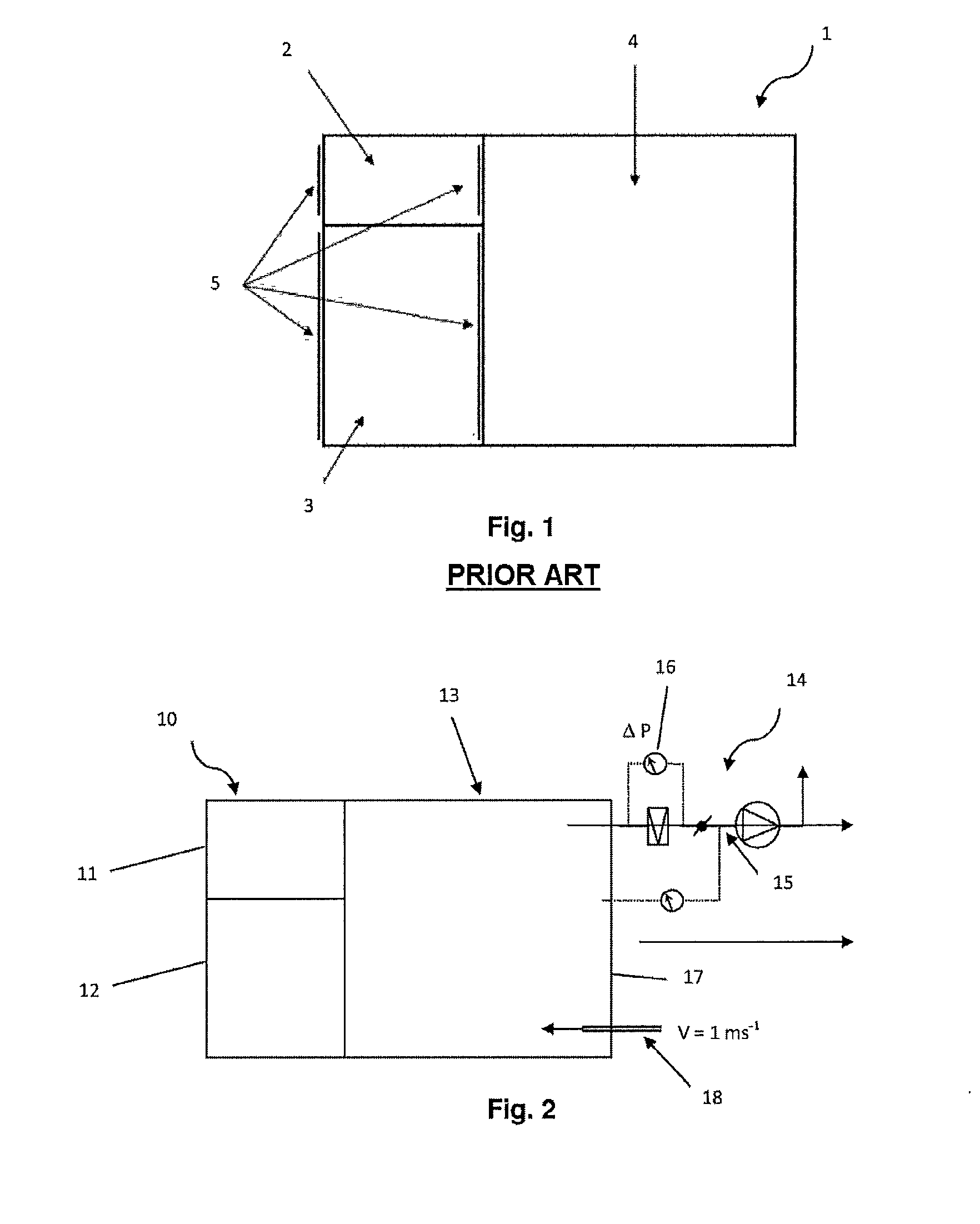
[0080]FIG. 2 shows an enclosure 10 which is at a reduced pressure in relation to the exterior surroundings according to one aspect of the presently disclosed embodiment.

[0081]This enclosure 10 comprises a metallic structure covered with sheets of vinyl delimiting a first airlock 11 for the circulation of one or more operator(s) and a second air lock 12 intended to accommodate and allow the removal of structural materials resulting from the cleaning up and / or the dismantling of contaminated elements, equipment or installations. The first and second air locks 11, 12 are separate from one another and not interconnected.

[0082]Purely by way of example, the volume of the first air lock 11 is 5 m3 while the volume of the second air lock 12 is 15 m3.

[0083]These vinyl walls also delimit a third air lock 13, referred to as the intervention air lock and having a greater volume than the other two, for example 40 m3.

[0084]O...


PUM


Abstract

The invention relates to a method and device for monitoring the confinement of an enclosure including walls delimiting an interior volume and an external environment, according to which a differential pressure (ΔP) is maintained between the interior volume and the external environment. According to the invention, the enclosure includes a port in one of the walls thereof establishing a fluid communication between the interior volume and the external environment, the port is traversed by a gas stream having a speed (V) at least equal to a reference speed Vréf, under the effect of the differential pressure (ΔP). Method according to which the following steps are performed, measuring the speed (V) of the gas stream at predetermined time intervals or continuously, and comparing the speed (V) measurement with reference speed Vréférence, and when the speed (V) measurement is less than reference speed Vréférence, transmitting at least one alarm signal.

Description

CROSS-REFERENCE TO RELATED APPLICATION[0001]This application is the National Stage of International Application No. PCT / EP2013 / 054064 having International filing date 28 Feb. 2013, which designated the United States of America, and which International Application was published under PCT Article 21 (s) as WO Publication 2013 / 127935 A1 and which claims priority from, and benefit of, French Application No. 1350149 filed on 8 Jan. 2013 and French Application No. 1251872 filed on 29 Feb. 2012, the disclosures of which are incorporated herein by reference in their entireties.BACKGROUND[0002]1. Field[0003]The presently disclosed embodiment relates to a method and a device for monitoring the dynamic confinement of a confinement enclosure that is at a raised or at a reduced pressure in relation to the exterior surroundings. The presently disclosed embodiment also relates to an enclosure equipped with such a confinement control device.[0004]2. Brief Description of Related Developments[0005]It...

Claims


Application Information

Patent Timeline
Patent Type & Authority Applications(United States)
IPC IPC(8): G01M3/00G01F1/00
CPCG01M3/00G01F1/00G21C17/002G21D1/003G21F7/00G21F7/015Y02E30/00Y02E30/30G21D1/00
Inventor DOMINIQUE, BOIS
Owner COMMISSARIAT A LENERGIE ATOMIQUE ET AUX ENERGIES ALTERNATIVES
Learn More