
Sliding block linkage folding bed

a technology of sliding block and folding bed, which is applied in the direction of rigid tables, nursing beds, medical science, etc., can solve the problems of limited use of head boards, many defects and limitations in the method, and large appearance and shape limitations, so as to eliminate the defects of the lifting structure of the head boards and effectively control the distance between the head boards. , the effect of seasoning the structur

Active Publication Date: 2015-01-08
KEESON TECH CORP LTD
View PDF2 Cites 68 Cited by
  • Summary
  • Abstract
  • Description
  • Claims
  • Application Information

AI Technical Summary

Benefits of technology

The technical effects of the invention are that it provides a sliding block linkage for an electric bed, which has a seasonable structure that solves defects in previous head board lifting structures. The linkage effectively controls the distance between the head board and the bed-rest, improving the comfort of the electric bed.

Problems solved by technology

Nonetheless, most electric beds have a problem at present, namely a head bed, bed frame, or a bracket is away from a bed-rest at a certain distance when the head board raises, in which case, it is possible that some articles such as a pillow, and etc. would fall into the bed frame through the gap with the bed-rest.
This method improves the above problems to some extent, but the distance from the bed-rest is not eliminated, many elastic materials are used, and appearance and shape are greatly limited.
Nonetheless, this method had many defects and limitations.
First, the structure and stress features limited use of the head board during beginning a raising stage.
Thus the distance is not controlled during the beginning raising stage of the head board, and the woven belts are loose, causing uncontrolled risks such as twisting and knotting.
Secondly, as the flexible woven belts bear tensile force only, it is impossible to solve the problem that the upper bed frame slides by force toward the bed-rest.

Method used


Image

  • Sliding block linkage folding bed
  • Sliding block linkage folding bed
  • Sliding block linkage folding bed

Examples


Embodiment Construction

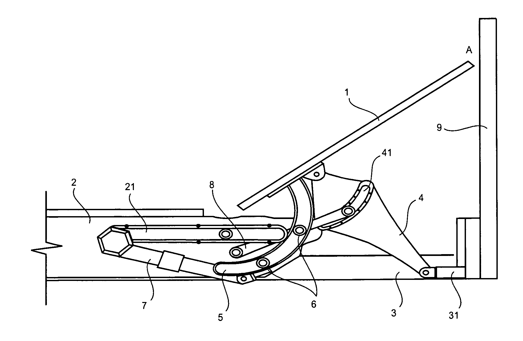
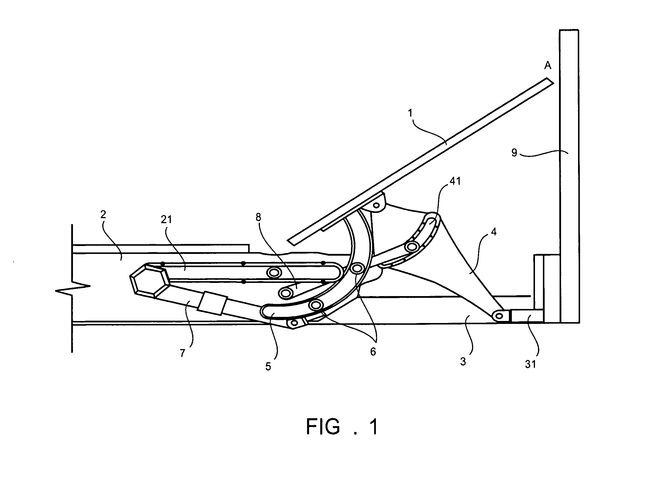
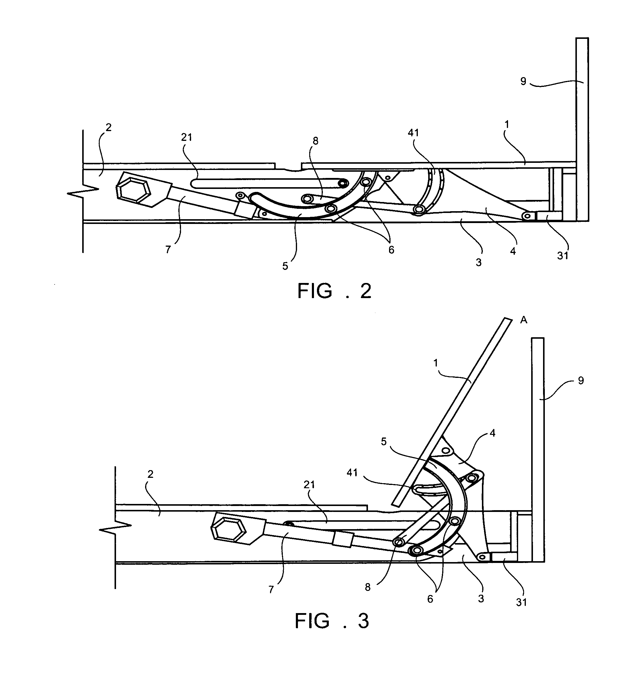
[0038]As shown in FIG. 1, FIG. 2, FIG. 3 and FIG. 4, the crank sliding block linkage 4 for the electric bed according to the invention comprises the head board 1 (in this embodiment, the head board provided with the bed board), the inner frame 2 and the outer frame 3. The inner frame 2 is positioned on the outer frame 3 and movably connected with it by the sliding chute 21. The inner frame 2 is driven by the motor to horizontally move relative to the outer frame 3. The crank sliding block linkage further comprises the head supporting part 4 (e.g. the crank), the push rod 7 (linear motor) and two hinge pins 6.

[0039]The head supporting part 4 can be a sliding block linkage formed as a crank 4. The head supporting part 4 is a generic name for the sliding block linkage, which in turn is a generic name for the crank 4. The crank 4 is the sliding block linkage, which is the head supporting part 4. The crank 4 is a part that supports the head by raising the headboard.

[0040]The head board m...


PUM


Abstract

An electric bed with a sliding block linkage has a head board, an inner frame, an outer frame, and a head supporting part. Two ends of the head supporting part are in rotatable connection with the head board and the outer frame. The inner frame is in sliding connection with the outer frame. The head board is in rotatable connection with the inner frame. A sliding block linkage has a driving device used for driving the inner frame to move relative to the outer frame. Relative sliding in a horizontal direction controls a horizontal movement distance of the head board. Optionally, the inner frame is positioned on the outer frame and movably connected with it by a sliding chute. The inner frame is driven by a motor to horizontally move relative to the outer frame.

Description

[0001]This application claims priority from and is a Paris Convention Treaty of non-provisional application of: People's Republic of China utility model patent application 201310281317.2 entitled Electric Bed, filed Jul. 10, 2013, by inventor Xu, Jianchun; the disclosures of which are incorporated herein by reference.FIELD OF THE INVENTION[0002]The invention relates to a driving mechanism for an electric bed, specifically a lifting mechanism for a head board, and particularly a sliding block linkage for the electric bed.BACKGROUND[0003]With increasing extreme obesity and an aging population, the electric bed has become a popular piece of furniture. Nonetheless, most electric beds have a problem at present, namely a head bed, bed frame, or a bracket is away from a bed-rest at a certain distance when the head board raises, in which case, it is possible that some articles such as a pillow, and etc. would fall into the bed frame through the gap with the bed-rest. Additionally, when the ...

Claims


Application Information

Patent Timeline
Patent Type & Authority Applications(United States)
IPC IPC(8): A61G7/015A61G7/018
CPCA61G7/018A61G7/015
Inventor XU, JIANCHUN
Owner KEESON TECH CORP LTD
Learn More