
Method and apparatus for providing test cases

a test case and apparatus technology, applied in the field of test cases, can solve the problems of unpractical method of generating test cases for respective execution paths by solving one by one constraint sets, low efficiency, complex logic and a large number of process branches, etc., and achieve the effect of improving the efficiency of providing test cases and promoting the regression test process of the program

Inactive Publication Date: 2015-01-01
IBM CORP
View PDF23 Cites 21 Cited by
  • Summary
  • Abstract
  • Description
  • Claims
  • Application Information

AI Technical Summary

Benefits of technology

The method and apparatus described in this patent text allow for the creation of a new test case for a modified part of a program without needing to regenerate new test cases for the entire program. This improves the efficiency of providing test cases and promotes the regression test process of the program.

Problems solved by technology

However, in order to meet various needs of users for software functions, many programs have complex logics and a large number of process branches.
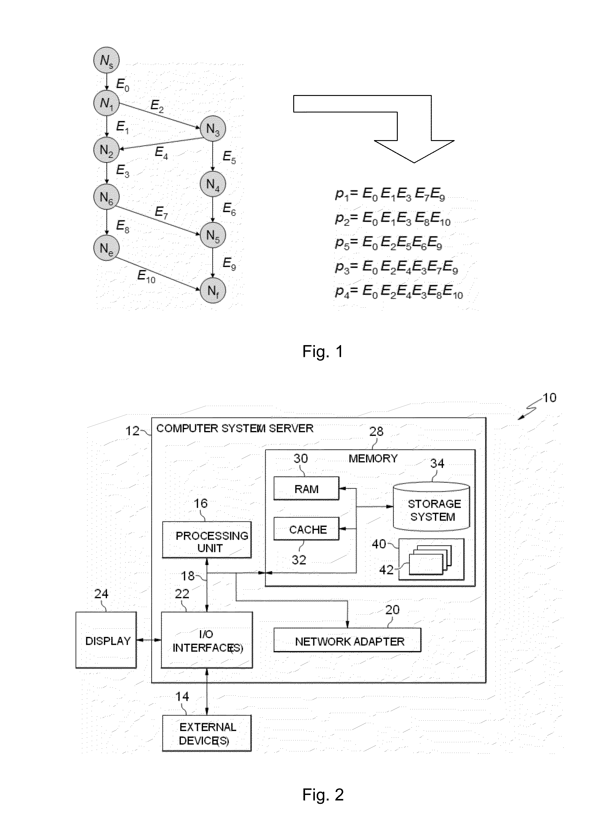
A large number of process branches can generate a huge number of execution paths, and this is also called path state space explosion.
For such cases, the method of generating test cases for respective execution paths by solving the constraint sets thereof one by one becomes unpractical because of low efficiency.
However, in practice, each modification to the program is likely to cause a change in execution paths of the program.
Therefore, it is possible that a test case applicable for a specific execution path in the original version of the program can no longer be applicable for the modified program, while on the contrary, an applicable test case could not be found for a new execution path generated due to a program change.
However, as mentioned before, on one hand, logics of programs are more and more complex, and the number of execution paths is huge; on the other hand, programs are modified very frequently.
These two factors make regenerating test cases for each modification of the program very costly.

Method used


Image

  • Method and apparatus for providing test cases
  • Method and apparatus for providing test cases
  • Method and apparatus for providing test cases

Examples


Embodiment Construction

[0022]Some preferable embodiments will be described in more detail with reference to the accompanying drawings, in which the preferable embodiments of the present disclosure have been illustrated. However, the present disclosure can be implemented in various manners, and thus should not be construed to be limited to the embodiments disclosed herein. On the contrary, those embodiments are provided for the thorough and complete understanding of the present disclosure, and completely conveying the scope of the present disclosure to those skilled in the art.

[0023]As will be appreciated by one skilled in the art, aspects of the present invention can be embodied as a system, method or computer program product. Accordingly, aspects of the present invention can take the form of an entirely hardware embodiment, an entirely software embodiment (including firmware, resident software, micro-code, etc.) or an embodiment combining software and hardware aspects that can all generally be referred t...


PUM


Abstract

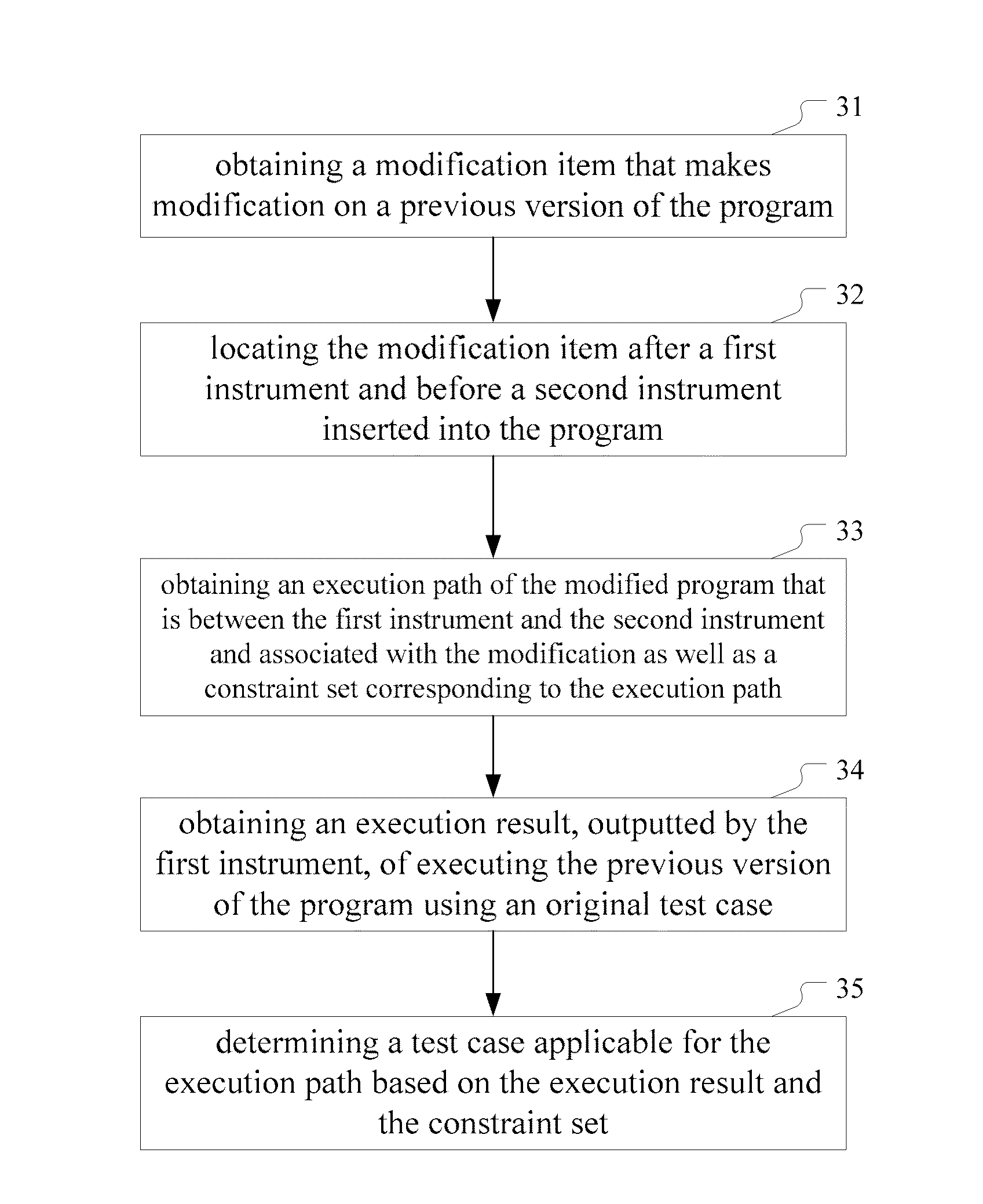
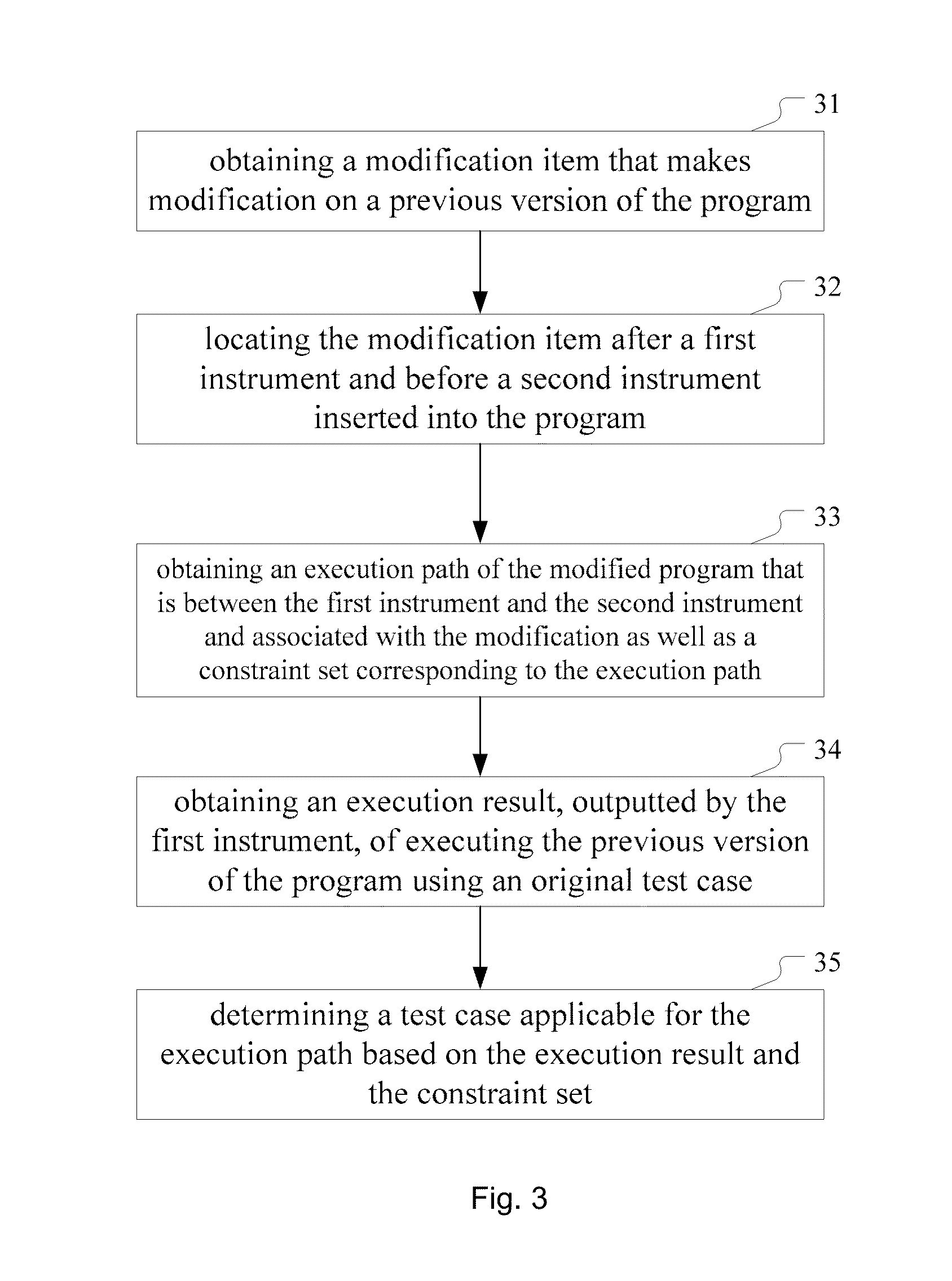
A method and apparatus for providing a test case for a modified program. The method includes the steps of: obtaining a modification item that makes modification on a previous version of the program; locating the modification item after a first instrument and before a second instrument of a plurality of instruments inserted into the program; obtaining an execution path of the modified program that is between the first instrument and the second instrument and associated with the modification as well as a constraint set corresponding to the execution path; obtaining an execution result, outputted by the first instrument, of executing the previous version of the program using an original test case; and determining a test case applicable for the execution path based on the execution result and the constraint set. The apparatus corresponds to the method.

Description

CROSS-REFERENCE TO RELATED APPLICATION[0001]This application claims priority under 35 U.S.C. §119 from Chinese Patent Application No. 201310257810.0 filed Jun. 26, 2013, the entire contents of which are incorporated herein by reference.BACKGROUND OF THE INVENTION[0002]1. Field of the Invention[0003]The present invention relates to test cases for software testing, and more specifically, to a method and apparatus for providing test cases.[0004]2. Brief Description of Related Art[0005]In the process of software development, developers write source codes of programs for functions to be implemented by software, and then testers use test cases to test software built based on source codes. It can be understood that a program usually constructs a plurality of flow branches by using, for example, condition judgment and jump statement, so as to form a plurality of execution paths. Therefore, it is desired to select appropriate test cases to constitute a test suite so that respective test case...

Claims


Application Information

Patent Timeline
Patent Type & Authority Applications(United States)
IPC IPC(8): G06F11/36
CPCG06F11/3684G06F11/3466
Inventor LI, QI CHENGMEI, LI JUNWANG, JIANXIE, FANG QUANZHU, ZI YU
Owner IBM CORP
Learn More