
Instrument for assaying radiation

a radiation assay and instrument technology, applied in the direction of instruments, photometry using electric radiation detectors, optical radiation measurement, etc., can solve the problems of inability to accurately know the specific location of radiation and/or contamination, the radiation and/or contamination area that requires decontamination or other remediation efforts, and the radiation and/or contamination levels are significan

Inactive Publication Date: 2015-01-01
SAVANNAH RIVER NUCLEAR SOLUTIONS
View PDF9 Cites 2 Cited by
  • Summary
  • Abstract
  • Description
  • Claims
  • Application Information

AI Technical Summary

Benefits of technology

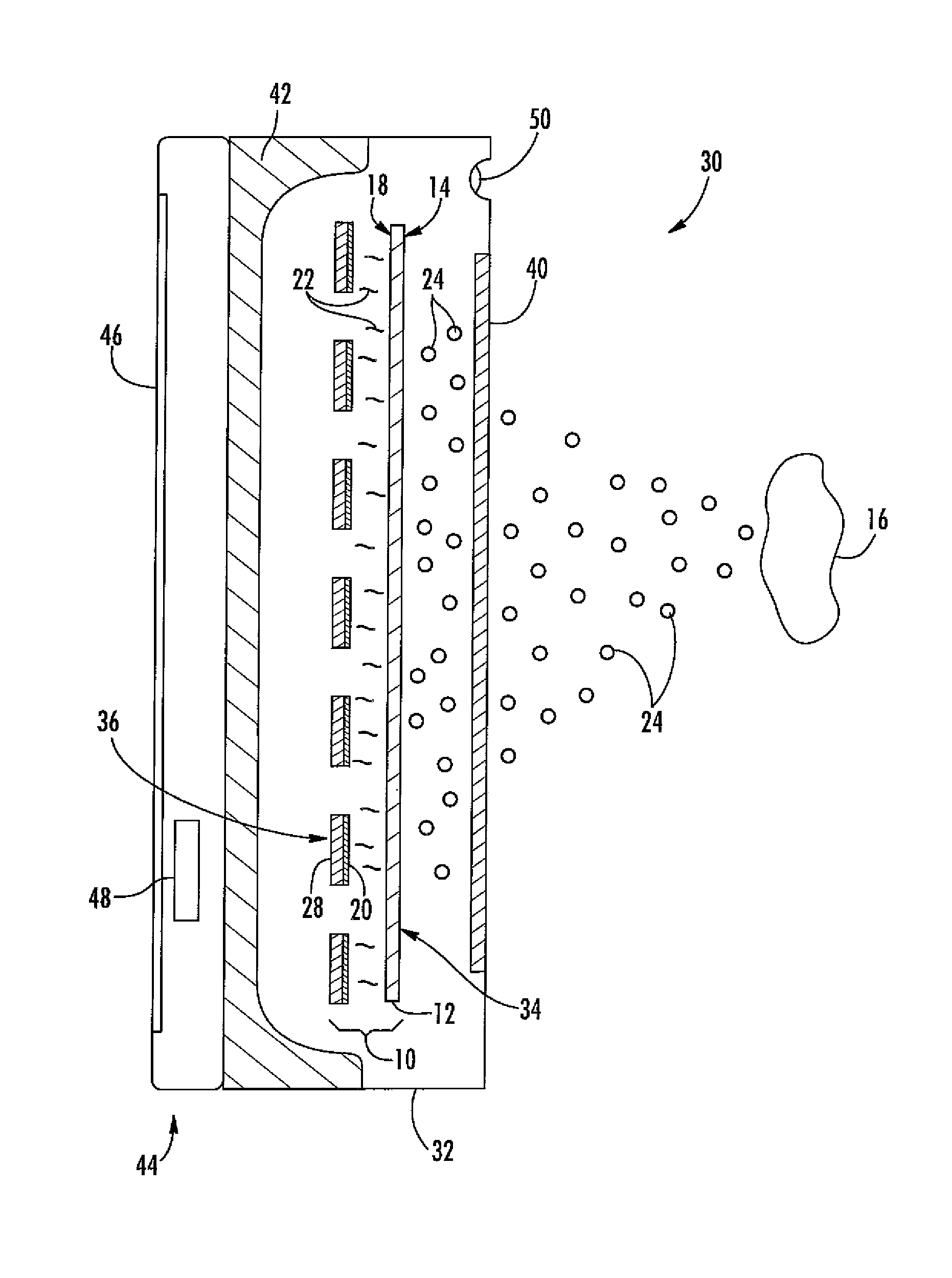
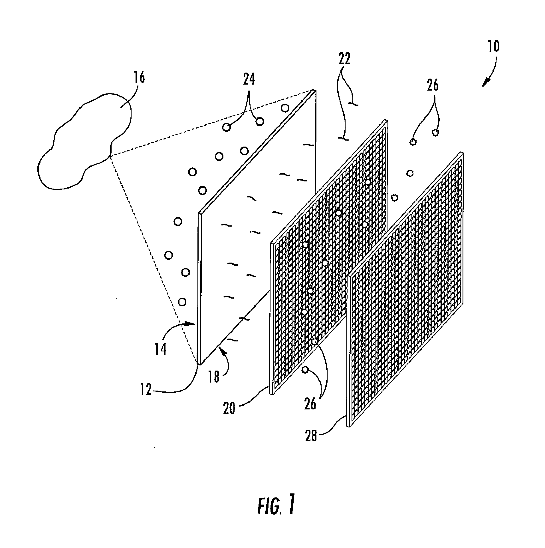
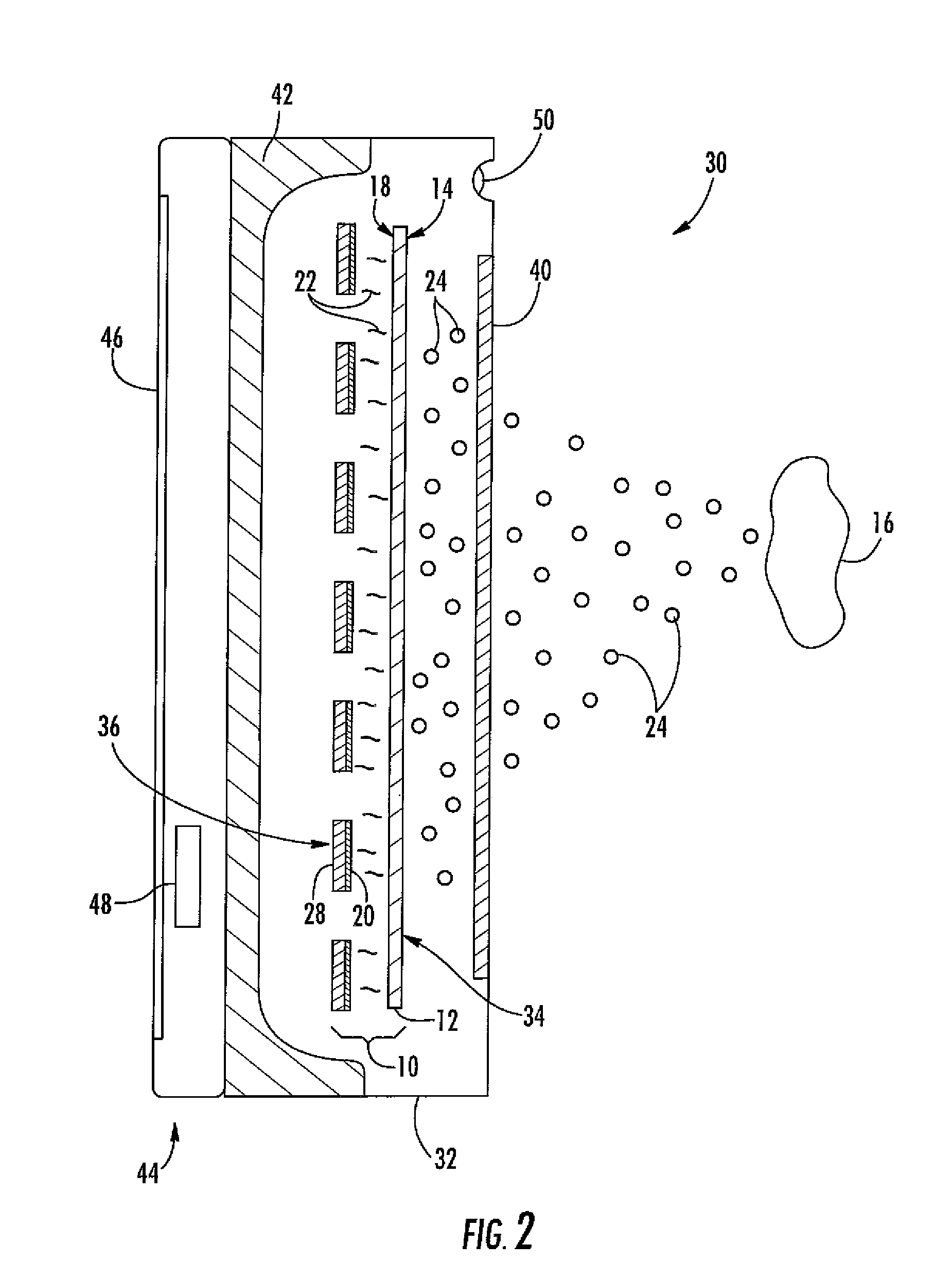
The present invention provides several different types of instruments for assessing radiation. These instruments use a flat panel detector with a collimated aperture covering at least a portion of its first side, and may also include a display screen or radiation shield to cover the second side of the detector. Additionally, the invention includes a scintillation layer with a collimated aperture covering its first side, and a photodiode layer with a collimated aperture covering its second side. The technical effects of these instruments are improved accuracy in measuring radiation, improved detection of radiation sources, and improved performance in identifying radiation sources.

Problems solved by technology

The use of radioactive material occasionally results in radiation and / or contamination areas that require decontamination or other remedial efforts.
In some cases, the radiation and / or contamination levels may be significant, and the specific locations of the radiation and / or contamination may not be accurately known.

Method used


Image

  • Instrument for assaying radiation
  • Instrument for assaying radiation
  • Instrument for assaying radiation

Examples


Embodiment Construction

[0015]Reference will now be made in detail to present embodiments of the invention, one or more examples of which are illustrated in the accompanying drawings. The detailed description uses numerical and letter designations to refer to features in the drawings. Like or similar designations in the drawings and description have been used to refer to like or similar parts of the invention. As used herein, the terms “first,”“second,” and “third” may be used interchangeably to distinguish one component from another and are not intended to signify location or importance of the individual components. The terms “upstream,”“downstream,”“radially,” and “axially” refer to the relative direction with respect to particle movement. For example, “upstream” refers to the direction from which the particle flows, and “downstream” refers to the direction to which the particle flows. Similarly, “radially” refers to the relative direction substantially perpendicular to the particle flow, and “axially” r...


PUM


Abstract

An instrument for assaying radiation includes a flat panel detector having a first side opposed to a second side. A collimated aperture covers at least a portion of the first side of the flat panel detector. At least one of a display screen or a radiation shield may cover at least a portion of the second side of the flat panel detector.

Description

FEDERAL RESEARCH STATEMENT[0001]This invention was made with Government support under Contract No. DE-AC09-08SR22470, awarded by the U.S. Department of Energy. The Government has certain rights in the invention.FIELD OF THE INVENTION[0002]The present invention generally involves an instrument for assaying radiation. In particular embodiments, the instrument may enable high resolution and / or real time mapping of a radiologically controlled area.BACKGROUND OF THE INVENTION[0003]The use of radioactive material occasionally results in radiation and / or contamination areas that require decontamination or other remedial efforts. In some cases, the radiation and / or contamination levels may be significant, and the specific locations of the radiation and / or contamination may not be accurately known. As a result, various instruments have been developed to assay radiation and contamination areas so that the costs and personnel exposures associated with the decontamination or other remediation e...

Claims


Application Information

Patent Timeline
Patent Type & Authority Applications(United States)
IPC IPC(8): G01T1/20G01T1/167
CPCG01T1/167G01T1/2018G01T1/169G01T1/2019
Inventor COLEMAN, JODY RUSTYNFARFAN, EDUARDO B.
Owner SAVANNAH RIVER NUCLEAR SOLUTIONS
Learn More