Operating a controller for an energy production plant
- Summary
- Abstract
- Description
- Claims
- Application Information
AI Technical Summary
Benefits of technology
Problems solved by technology
Method used
Image
Examples
Embodiment Construction
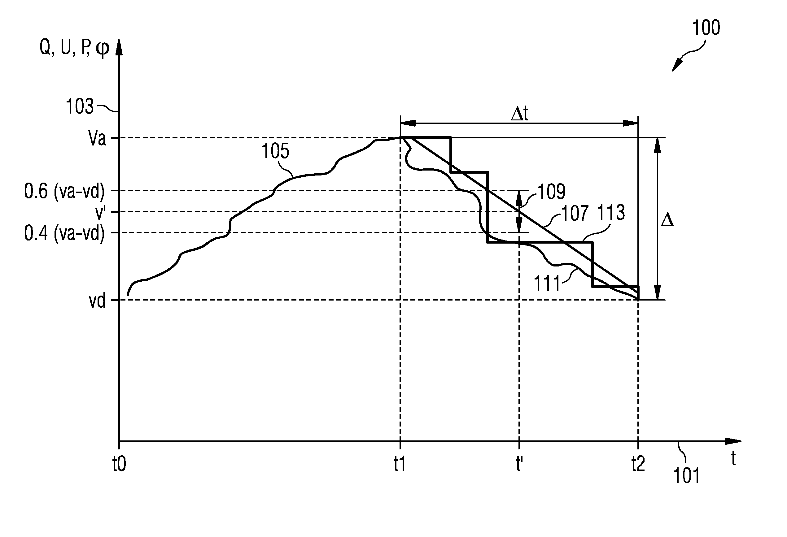
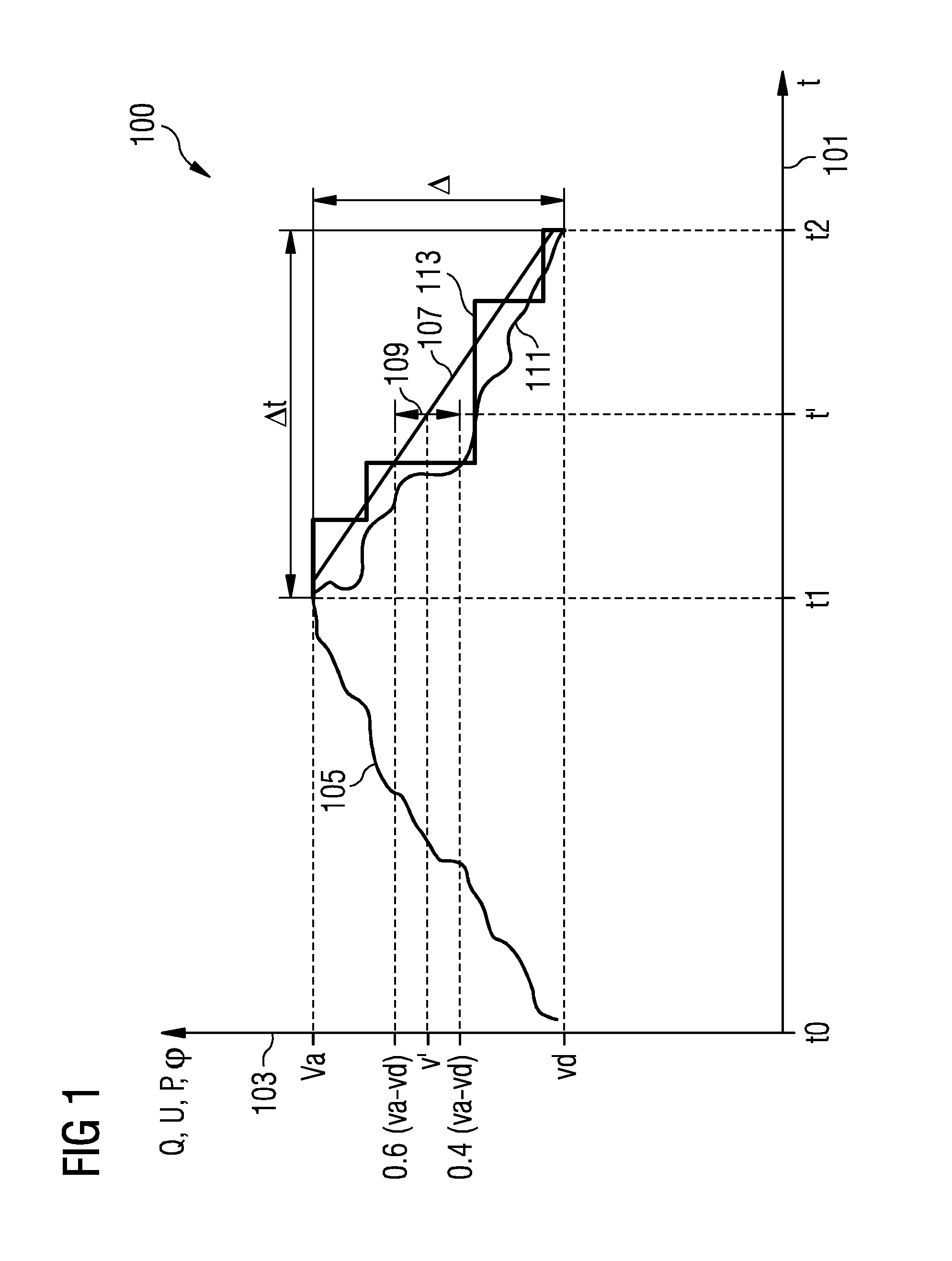
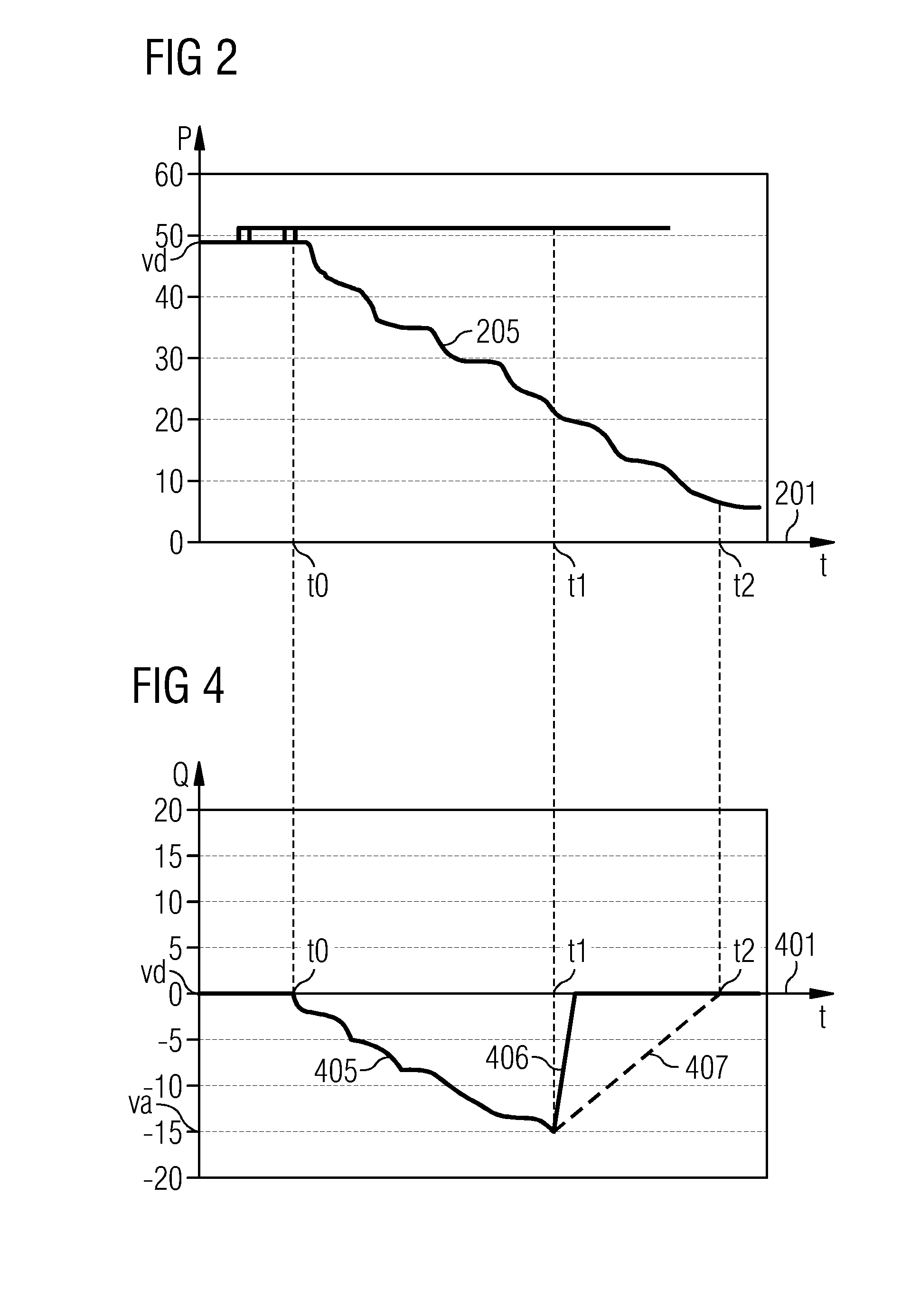
[0059]FIG. 1 illustrates a graph considered in a method of operating a controller according to an embodiment of the present invention. On an abscissa 101 the time t is indicated, while on an ordinate 103 the reactive power Q, the voltage U, the active power P, or the power factor φ or cos(φ) are indicated. The method may be applied for controlling the reactive power Q and / or the voltage U and / or the active power P and / or the power factor φ. At a time point t0 a failure occurs, while the desired value, of e.g. the reactive power, vd is received as a signal (signal 217 in FIG. 2), e.g. from a grid operator (such as grid operator 219 in FIG. 2). The failure takes place between the time points t0 and t1. During the time interval between t0 and t1 the actual value (such as measured at the common node 202 in FIG. 2) changes according to the curve 105 which reaches the actual value va at the first time point t1. In particular, the actual value va may be received from a measurement equipmen...
PUM
 Abstract
Description
Claims
Application Information
 - R&D
- Intellectual Property
- Life Sciences
- Materials
- Tech Scout
- Unparalleled Data Quality
- Higher Quality Content
- 60% Fewer Hallucinations
Browse by: Latest US Patents, China's latest patents, Technical Efficacy Thesaurus, Application Domain, Technology Topic, Popular Technical Reports.
© 2025 PatSnap. All rights reserved.Legal|Privacy policy|Modern Slavery Act Transparency Statement|Sitemap|About US| Contact US: help@patsnap.com


