
Shaving blade assembly with a blade unit and a skin contact member

a blade unit and skin contact technology, applied in the direction of metal working devices, etc., can solve the problems of shaving blade assemblies that do not provide shaving in good conditions, user nicks and cuts, and wear of shaving aids, so as to prevent intense skin deformation, reduce manufacturing costs, and enhance shaving. the effect of gliding

Active Publication Date: 2014-12-25
BIC VIOLEX SA
View PDF6 Cites 5 Cited by
  • Summary
  • Abstract
  • Description
  • Claims
  • Application Information

AI Technical Summary

Benefits of technology

The present invention relates to shaving blade assemblies with a skin contact member that prevents hard pressure and damage to the skin during shaving. The skin contact member acts like a stretcher on the skin, allowing for enhanced gliding and safety during shaving. The manufacturing costs of the shaving blade assembly with the skin contact member are generally cheaper than prior art. The skin contact member can be produced in a single production step, which means lower production cost and easier quality control. The advantages of the present invention include a pleasant feeling of enhanced gliding, safety for the skin, the lack of damage to the skin, and absorption of excessive pressure that might provoke micro injuries and / or irritation on the skin. The distance between the contact plane and the shaving plane is preferably between 0.2 mm and 0.6 mm to allow for a fast, smooth, and safer shave.

Problems solved by technology

However, the shaving aid gets worn out, changing the dimensions of the shaving aid with respect to the blade assembly, and as a result, the user can experience nicks and cuts from the shave.
Therefore, the known shaving blade assemblies do not provide shaving in good conditions as soon as the shaving aid becomes worn.
In addition, the manufacture of such known shaving blade assemblies is complicated since the skin contact member is commonly made of several materials (double and triple injection molding) and / or since a shaving aid is added on the skin contact member.

Method used


Image

  • Shaving blade assembly with a blade unit and a skin contact member
  • Shaving blade assembly with a blade unit and a skin contact member
  • Shaving blade assembly with a blade unit and a skin contact member

Examples


Embodiment Construction

[0048]The embodiments of the present invention will now be described more fully hereinafter with reference to the accompanying drawings, in which preferred embodiments of the invention are shown. This invention may, however, be embodied in many different forms and should not be construed as limited to the illustrated embodiments set forth herein. Rather, these illustrated embodiments are provided so that this disclosure will be thorough and complete and will convey the scope of the invention to those skilled in the art.

[0049]In the following description, like reference characters designate like or corresponding parts throughout the figures. Additionally, in the following description, it is understood that terms such as “top,”“bottom,”“side,”“front,”“back,”“inner,”“outer,” and the like, are words of convenience and are not to be construed as limiting terms.

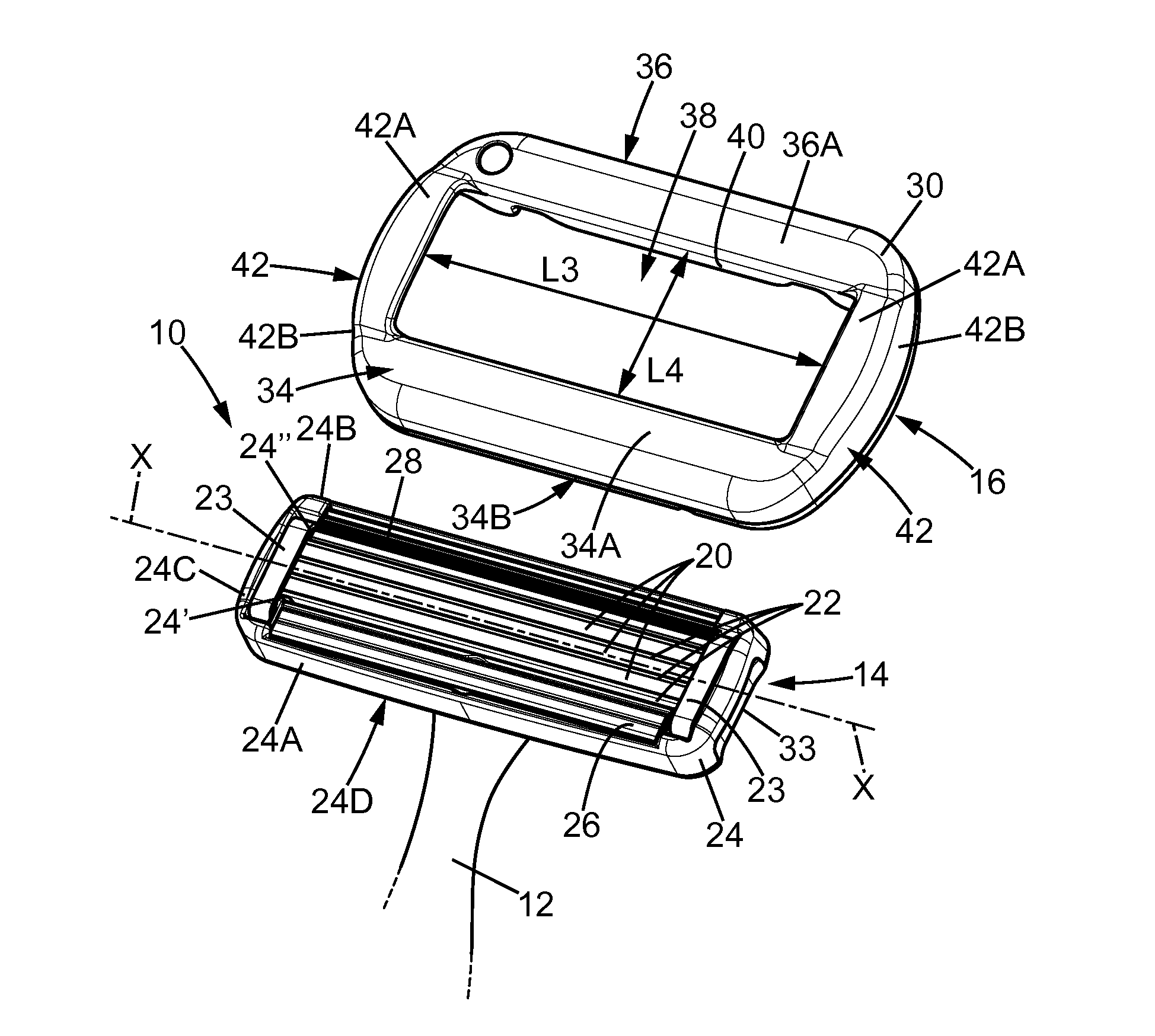
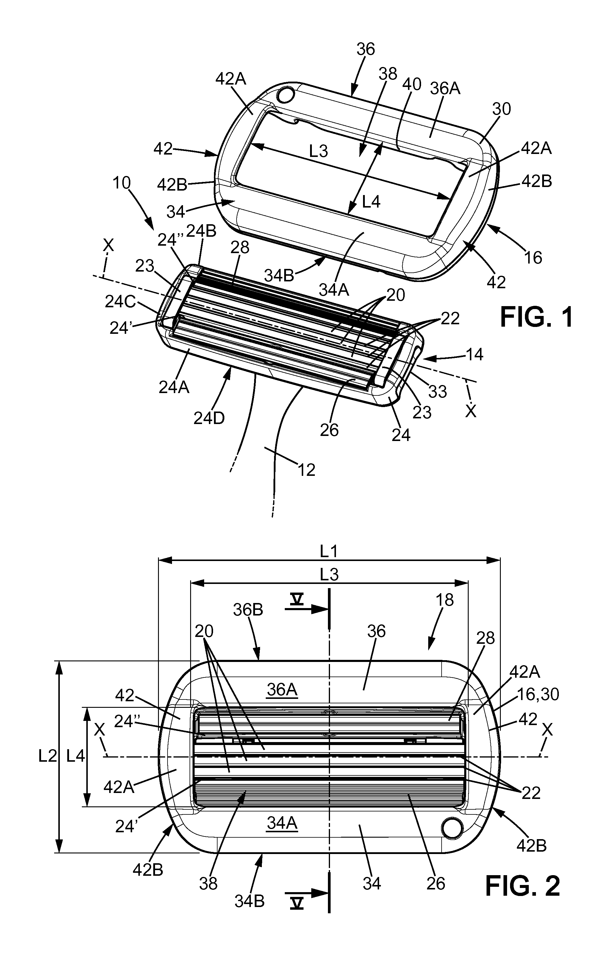
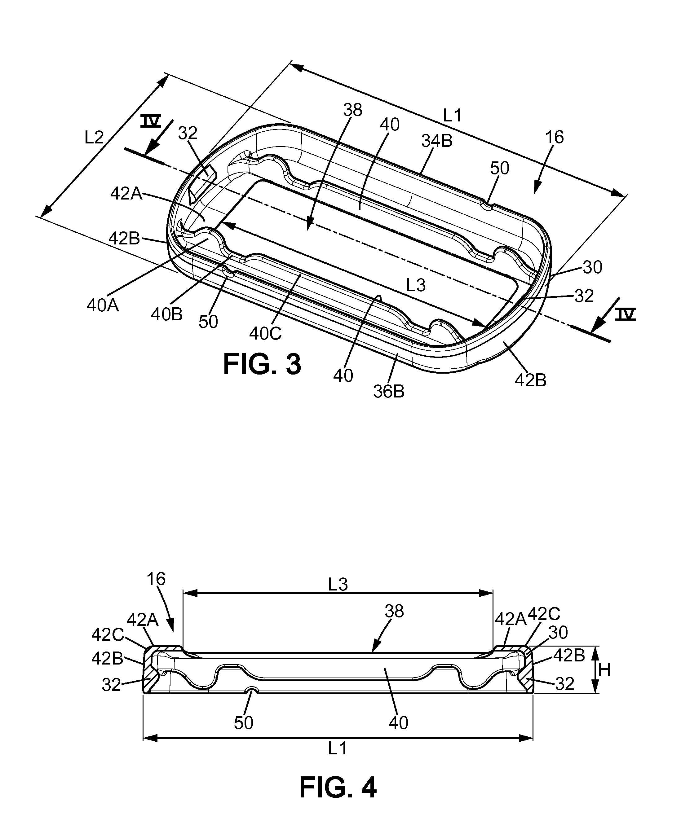
[0050]The figures illustrate a razor 10 according to an embodiment of the present invention, including a razor handle 12, a shavi...


PUM


Abstract

A shaving blade assembly including a blade unit and a skin contact member. A razor including a razor handle and such a shaving blade assembly. The blade unit includes at least one shaving blade having a cutting edge. The blade unit has a blade unit skin contact surface area, where the blade unit and the skin contact member have a shaving blade assembly skin contact surface area. The ratio between the shaving blade assembly skin contact surface area and the blade unit skin contact surface area is between approximately 2 and 3.1. The skin contact member can include a leading planar surface and a trailing planar surface defining a contact plane, and the contact plane and the shaving plane are parallel and the distance between the contact plane and the shaving plane is between approximately 0.2 mm and 0.6 mm.

Description

CROSS-REFERENCE TO RELATED APPLICATIONS[0001]This application is a continuation-in-part of U.S. patent application Ser. No. 13 / 922,882, which was filed in the U.S. Patent and Trademark Office on Jun. 20, 2013.FIELD OF THE INVENTION[0002]The invention relates to a shaving blade assembly including a blade unit and a skin contact member, and a razor including a razor handle and such a shaving blade assembly.BACKGROUND OF THE INVENTION[0003]The shaving blade assemblies of the prior art commonly include a skin contact member provided with a shaving aid such as a lubricant, a moisturizer, a conditioner and / or an exfoliant to improve the gliding of the razor when shaving.[0004]However, the shaving aid gets worn out, changing the dimensions of the shaving aid with respect to the blade assembly, and as a result, the user can experience nicks and cuts from the shave.[0005]Therefore, the known shaving blade assemblies do not provide shaving in good conditions as soon as the shaving aid becomes...

Claims


Application Information

Patent Timeline
Patent Type & Authority Applications(United States)
IPC IPC(8): B26B21/40
CPCB26B21/4031B26B21/44B26B21/40
Inventor BOZIKIS, IOANNIS
Owner BIC VIOLEX SA
Learn More