
Insert for bellows with non-linear compression / expansion in a vacuum powered tool

a vacuum-powered tool and inserting technology, which is applied in the direction of manufacturing tools, couplings, machines/engines, etc., can solve the problems that different types of articles and packages are not equally suitable for being gripped by means of negative pressure and suction

Active Publication Date: 2014-12-11
PIAB
View PDF3 Cites 12 Cited by
  • Summary
  • Abstract
  • Description
  • Claims
  • Application Information

AI Technical Summary

Benefits of technology

This patent describes a solution for adjusting a tool without having to remove the tool from the device. This is achieved by using a bellows that can be compressed or expanded depending on the type of object being handled. An insert is used to fill the pleats of the bellows and it is easy to install and remove without damaging the bellows. This allows for a quick adjustment of the tool without having to dismount the whole device.

Problems solved by technology

Various types of articles and packages are, however, not equally suitable to be gripped by means of negative pressure and by a suction effect.

Method used


Image

  • Insert for bellows with non-linear compression / expansion in a vacuum powered tool
  • Insert for bellows with non-linear compression / expansion in a vacuum powered tool
  • Insert for bellows with non-linear compression / expansion in a vacuum powered tool

Examples


Embodiment Construction

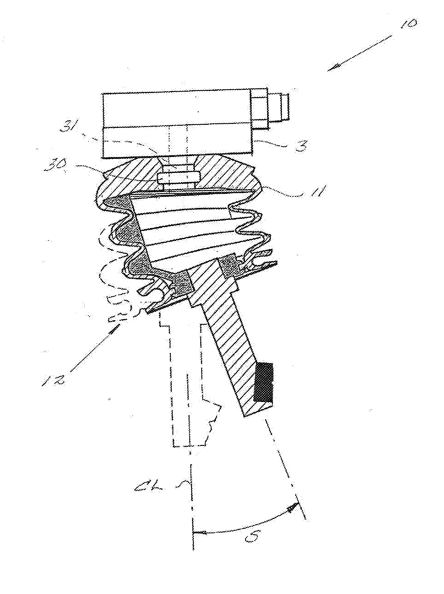
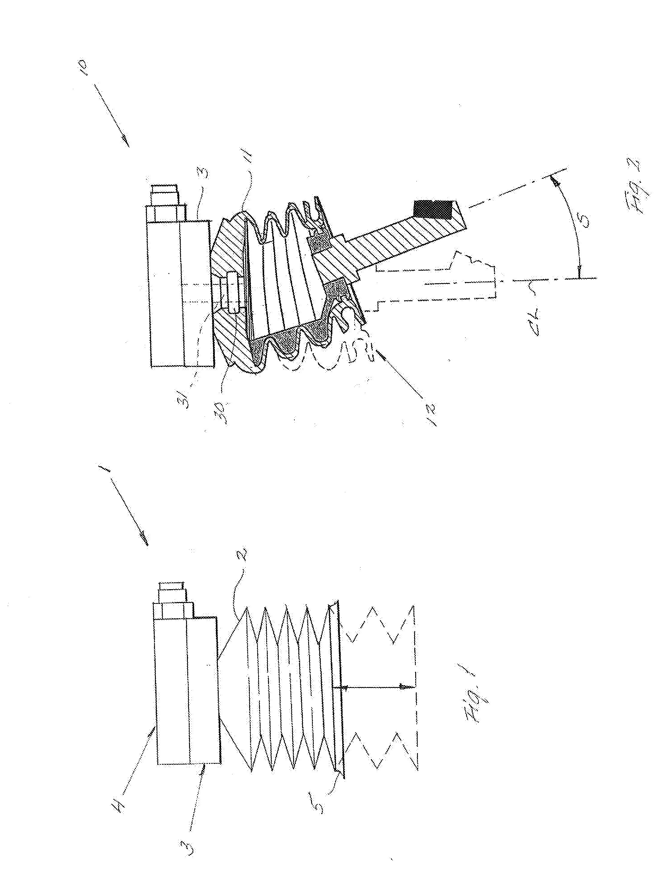
[0034]In FIG. 1, there is illustrated the typical mode of operation well known to a person skilled in the art of a conventional bellows in a vacuum powered tool generally designated by the reference numeral 1.

[0035]The bellows 2 is carried by a holder 3, which in itself usually is movable and controlled to act on an object gripped by the bellows. To the holder, a vacuum source is connected, from where negative pressure can be introduced into the bellows via an opening in the coupled end of the bellows. The vacuum source may be an ejector 4 integrated in the holder, but may alternatively be a pump or ejector that is placed outside the holder and from which negative pressure is led up to the bellows via a pipe. The free end of the bellows may be formed with a sealing ring 5 for air-proof contact with the surface of an object. The sealing ring 5 may be integrated in the bellows or be a separate ring or suction cup coupleable to the bellows.

[0036]By a solid line, a state is shown in FIG...


PUM


Abstract

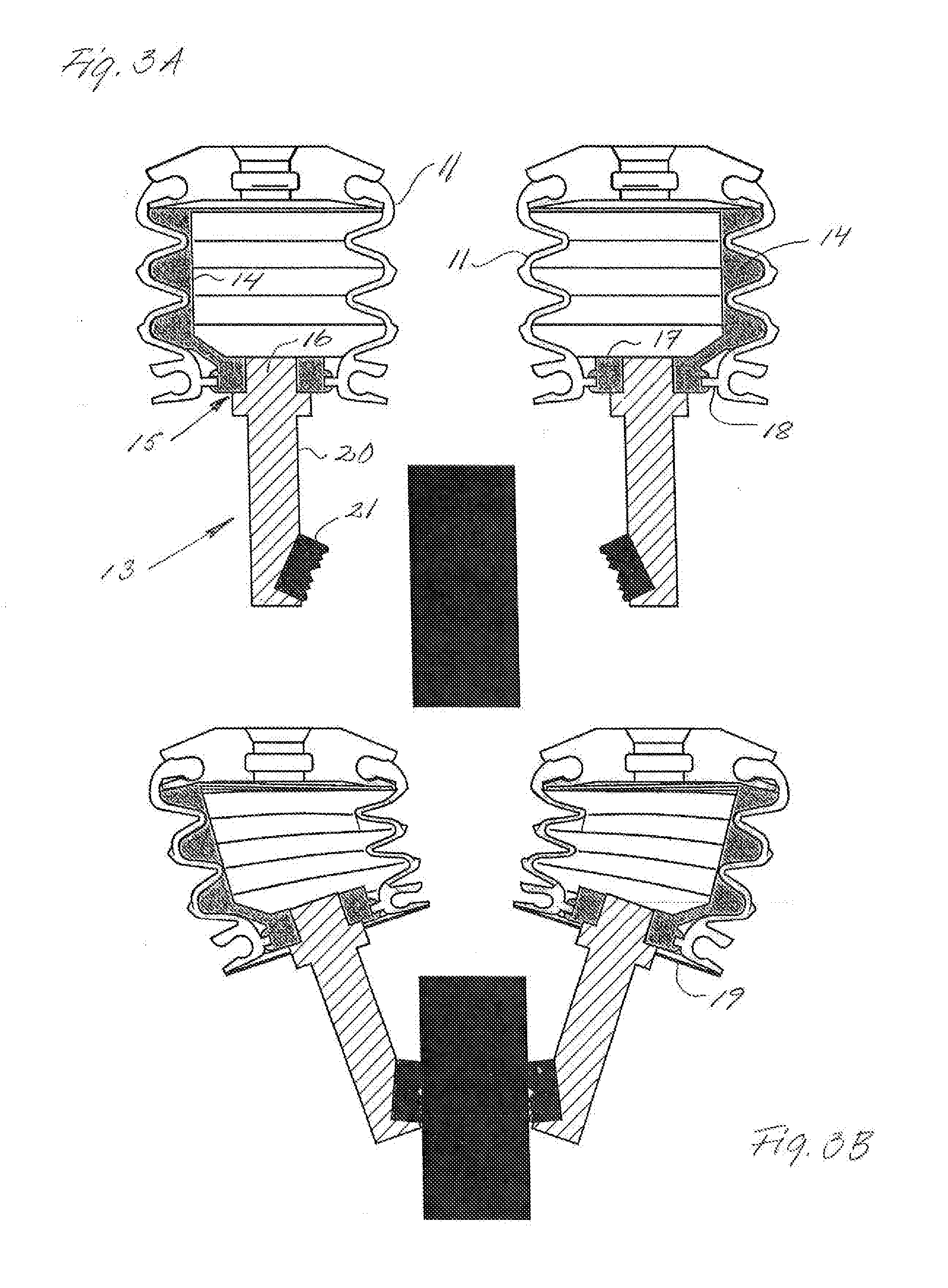
A bellows insert (25) is shown, mountable inside a bellows for a vacuum powered tool and, in the mounted position, effective to locally limit the capacity of the bellows of compression in its longitudinal direction caused by a negative pressure introduced into the bellows. The bellows insert includes an engagement part (26) that has a shape complementary to the inside of the bellows and that, in the mounted position of the bellows insert, fills up some or all of the pleats of the bellows, within a limited area of the circumference of the bellows.

Description

TECHNICAL FIELD[0001]The invention relates generally to vacuum powered tools. More precisely, the invention relates to a vacuum powered tool having a bellows that is connectable to a vacuum source and arranged to be compressed in its longitudinal direction as a result of a negative pressure in the bellows as well as to resiliently return to the original length when the negative pressure ceases. In an additional aspect, the invention relates to a bellows insert that is separately introducible into a bellows for vacuum powered tools.BACKGROUND AND PRIOR ART[0002]Vacuum powered tools are supplied with negative pressure from a vacuum source, which may be an ejector arranged adjacent to the tool or a centrally arranged ejector or pump that serves several gripping appliances. An appliance, such as a suction cup, can be connected to the vacuum source in order to, by suction effect, generate an engagement with objects that are to be handled by the vacuum powered tool.[0003]In vacuum powered...

Claims


Application Information

Patent Timeline
Patent Type & Authority Applications(United States)
IPC IPC(8): F16J3/06
CPCF16J3/06B25J15/0023B25J15/12F16D3/845B25J15/0475F16J3/043B25B5/061B25B11/005B25J15/0616B65B35/18B65G47/90B65G47/91B66C1/02F15B15/10
Inventor TELL, PETER
Owner PIAB
Learn More