
Redesigned AR-15 Upper Receiver

a technology of upper receiver and barrel nut, which is applied in the direction of breech mechanism, weapon components, weapon attachment points, etc., can solve the problems of time-consuming and stressful process of removing gas system and barrel nut, and the attachment point on the standard upper receiver is considerably thin and prone to cracking

Active Publication Date: 2014-12-04
FRITZ CRAIG ALLAN
View PDF11 Cites 36 Cited by
  • Summary
  • Abstract
  • Description
  • Claims
  • Application Information

AI Technical Summary

Benefits of technology

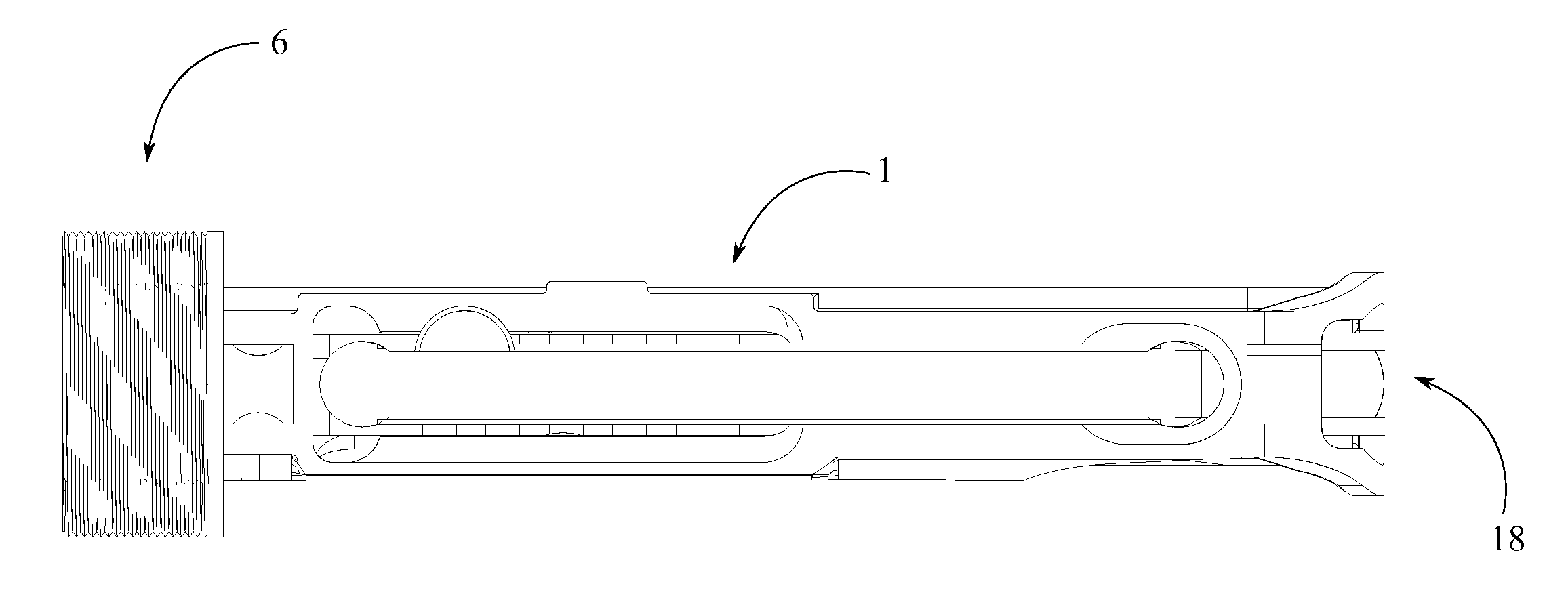
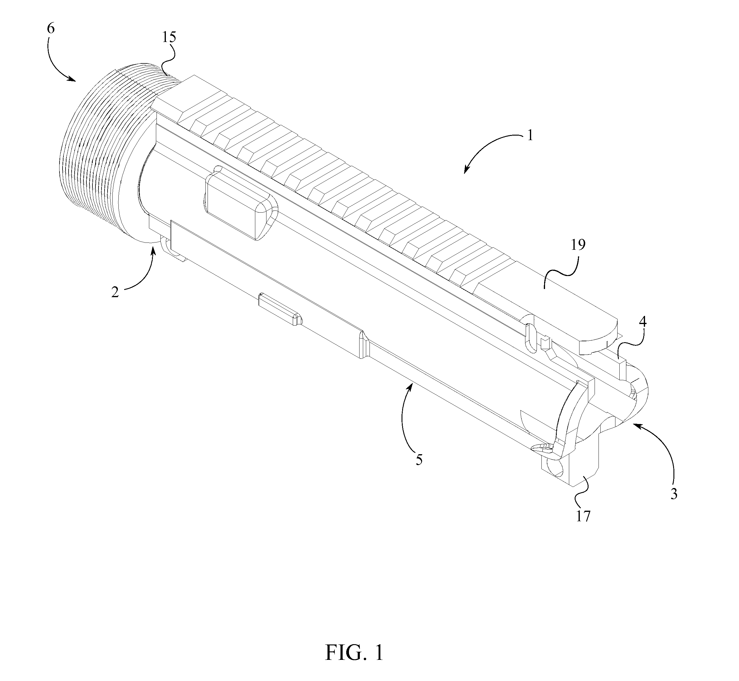
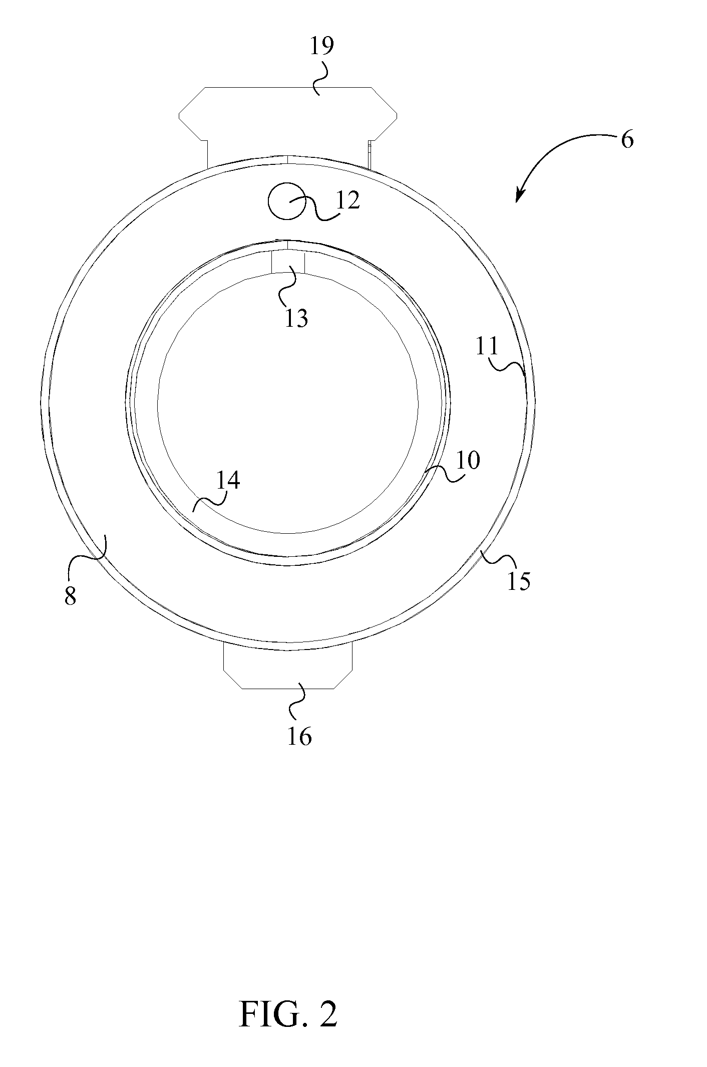
The present invention is a redesigned upper receiver for the AR-15 semi-automatic rifle. The invention provides a stronger barrel mount and eliminates the need to remove the gas system when switching barrels. The invention also has a series of other advantages such as being more flexible, durable, reliable, and easy to clean. The invention includes a cylindrical housing, a barrel mount, a first lower-receiver attachment point, a second lower-receiver attachment point, a stock mounting point, and a Picatinny-style rail. The invention allows for convenient interchange of barrels without interrupting the gas system.

Problems solved by technology

The attachment point on the standard upper receiver is considerably thin and is prone to cracking.
As a result of the lack of strength, parts need to be replaced on a regular basis.
The process of removing the gas system and the barrel nut can be time consuming and stressful.
The time consuming nature of the process can be disadvantageous to an individual who disassembles AR-15s on a regular basis.
Furthermore, due to the thin attachment point provided on a standard AR-15, repeated changing of barrels can affect life span of the weapon due to cracking.
The tedious process of aligning and tightening of components needs to be repeated since the entire gas system is removed along with the barrel.
As a result of the repeated use, even the components that were not replaced wear off to some extent.

Method used


Image

  • Redesigned AR-15 Upper Receiver
  • Redesigned AR-15 Upper Receiver
  • Redesigned AR-15 Upper Receiver

Examples


Embodiment Construction

[0013]All illustrations of the drawings are for the purpose of describing selected versions of the present invention and are not intended to limit the scope of the present invention.

[0014]The present invention is a redesigned upper receiver for the AR-15 semi-automatic rifle. The present invention provides more strength to the barrel mount and also eliminates the need to remove the gas system when switching barrels. Furthermore, the redesigned upper receiver has a series of other advantages. The convenience in cleaning, the ability to remove and clean the barrel extension in a short time period, the rigidity, higher accuracy levels and the ability to receive a variety of barrels are some notable advantages.

[0015]As seen in FIGS. 1, 2, and 3, the present invention comprises a cylindrical housing 1, a barrel mount 6, a first lower-receiver attachment point 16, a second lower-receiver attachment point 17, a stock mounting point 18, and a Picatinny-style rail 19. The barrel mount 6 and ...


PUM


Abstract

A redesigned upper receiver for the AR-15 upper receiver has a cylindrical housing, a barrel mount, and a stock mounting point. The barrel mount and the stock mounting point are positioned on opposite ends of the cylindrical housing. The AR-15 gun barrel is connected to the barrel mount. The charge carrier is inserted to the upper receiver through the stock mounting point. The barrel mount has a tubular body, a gas tube slot, a pin locking slot, an internal threading, and an external threading. The radius of the tubular body is larger than the cylindrical housing. The AR-15 gun barrel is secured within the internal threading. The gas tube is inserted to the gas tube slot. The hand guard is threaded onto the external threading of the upper receiver.

Description

[0001]The current application claims a priority to the U.S. Provisional Patent application Ser. No. 61 / 829,700 filed on May 31, 2013.FIELD OF THE INVENTION[0002]The present invention relates generally to the field of semi-automatic rifles. More specifically, the present invention is a redesigned upper receiver for the AR-15 rifle.BACKGROUND OF THE INVENTION[0003]The AR-15 was first built as a small arms rifle for the United States armed forces. Later on, the AR-15 was made available for civilian sales in 1963. As in most rifles, the AR-15 uses an operation mechanism called direct gas impingement, in which gas from a fired cartridge is directly guided to the bolt carrier or slide assembly to cycle the action. The AR-15 is designed such that one upper receiver can quickly and easily be substituted for another. Therefore, the upper receiver can incorporate barrels of different weights, lengths, and calibers.[0004]The barrel of the AR-15 is attached to the front end of the upper receive...

Claims


Application Information

Patent Timeline
Patent Type & Authority Applications(United States)
IPC IPC(8): F41A3/66F41A5/00
CPCF41A5/00F41A3/66F41A5/18
Inventor FRITZ, CRAIG A.LAFFE, BARRY D.
Owner FRITZ CRAIG ALLAN
Learn More