
Touch pen structure

a pen and pen body technology, applied in the pen field, to achieve the effect of increasing the holding strength and stability, and convenient us

Inactive Publication Date: 2014-11-27
WU CHI MING
View PDF2 Cites 11 Cited by
  • Summary
  • Abstract
  • Description
  • Claims
  • Application Information

AI Technical Summary

Benefits of technology

The present invention provides a touch pen structure that can be used on a touch panel and paper without needing to turn the main body. The structure is smooth and easily gripped, which makes it convenient to use and increases the holding strength and stability compared to previous touch pen structures. Overall, the touch pen structure provided by the present invention is new and practical in use.

Problems solved by technology

A conventional touch pen structure used for sliding and pressing on a touch panel is installed with a soft pad at the top of a main body thereof, a structural space formed at the bottom of the main body has to be reserved for accommodating and exposing a pen core, so the soft pad used for operating the touch screen is unable to be installed at the bottom of the main body, the conventional touch pen is limited to a rotary structure, a retractable structure (i.e. the pen core being pressed for exposing) having a press button at the top is unable to be adopted, so the soft pad is installed at the top thereby allowing the pen core to be protruded at the bottom, the touch pen structure is very much restrained, when a use desires to use the touch pen to operate the touch panel, the first step is to turn the main body having the pen core at the bottom, so the soft pad installed at the top of the main body is enabled to be faced downward, when the user desires to use the pen core for writing and recording the data shown in the touch panel, the user has to turn the main body one more time for allowing the pen core of the main body to be faced downward so as to be used for writing on paper, furthermore, for enabling the main body to meet the ergonomic requirement so as to achieve the objectives of easy to hold and stable in use, the top portion and the lower portion of the main body are often designed in different shapes, in a conventional touch pen which is aimed to provide functions of writing on paper and sliding and pressing on the touch panel, the soft pad has to be installed at the top of the main body and is unable to be installed at the bottom of the main body, as such, when the user uses the soft pad installed at the top of the main body, he has to hold at a location of the main body opposite to the location being held for writing, so complying with the ergonomic requirement is not achieved, and problems such as inadequate effort for holding, unstable operating, uncomfortable in use or even damage may occur; when in use, if writing on paper and sliding and pressing the touch panel for displaying data are both required to be operated, the main body has to be repeatedly turned, thereby wasting time and effort in use and causing inconvenience, the operation efficiency and practicability are severely affected.

Method used


Image

  • Touch pen structure
  • Touch pen structure
  • Touch pen structure

Examples


Embodiment Construction

[0033]The accompanying drawings are included to provide a further understanding of the invention, and are incorporated in and constitute a part of this specification. The drawings illustrate embodiments of the invention and, together with the description, serve to explain the principles of the invention. The accompanying drawings are only served for illustration; in actual practice, the relative ratio and precision arrangement of disclosed components and the scope of the present invention shall not be limited to the provided drawings.

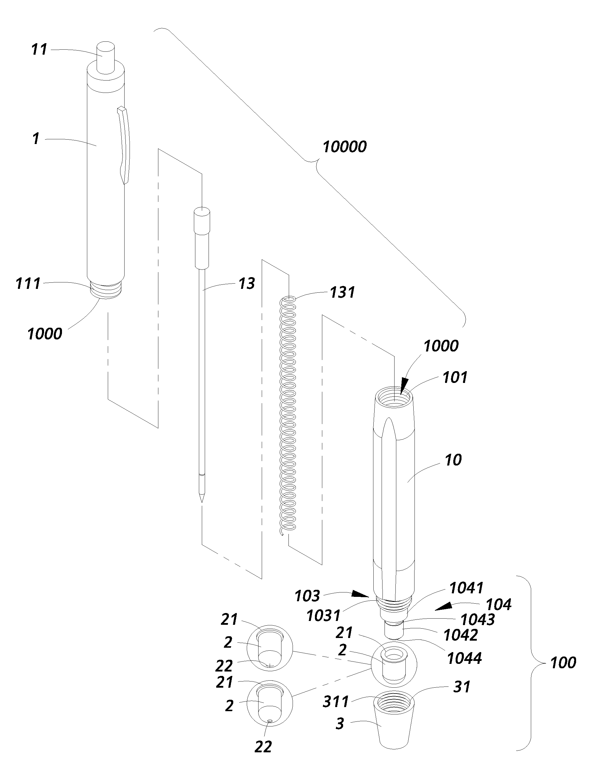
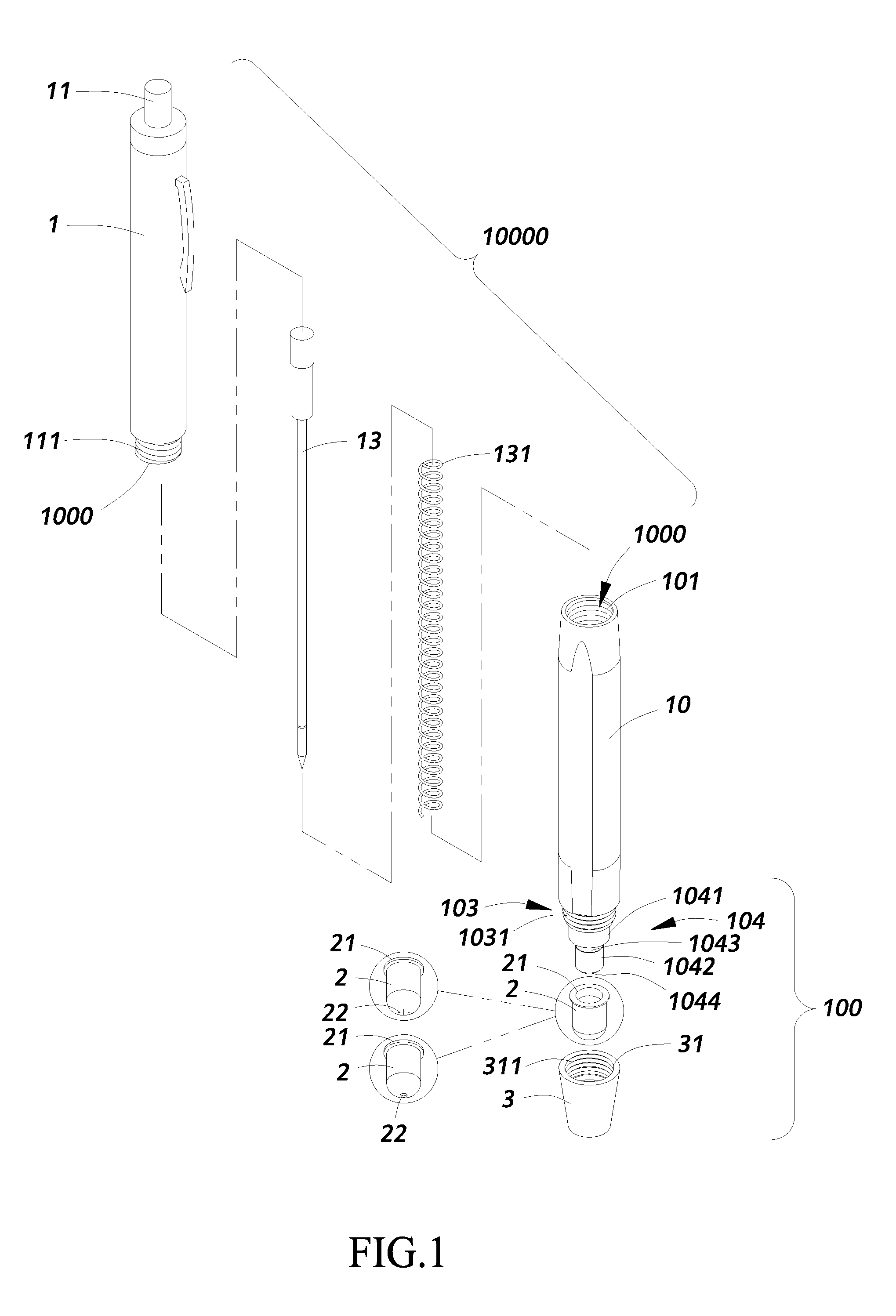
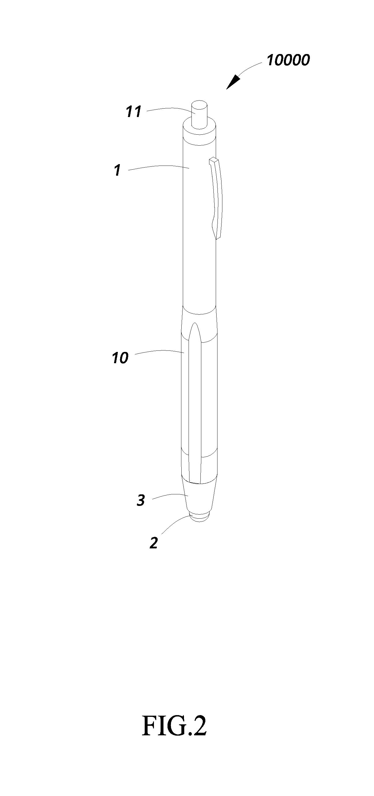
[0034]Referring from FIG. 1 to FIG. 6, wherein FIG. 1 is a perspective exploded view showing the touch pen structure according to one embodiment of the present invention; FIG. 2 is a perspective view showing the assembly the touch pen structure according to one embodiment of the present invention; FIG. 3 is a cross sectional view showing the assembly the touch pen structure according to one embodiment of the present invention; FIG. 4 is a perspective ex...


PUM


Abstract

The present invention provides a touch pen structure, especially to a touch pen structure which can be used for replacing fingers to operate a touch screen, which includes: a main body, at least a pen core, an electric conductive touch sleeve and an end cap. The electric conductive touch sleeve and the pen core are installed at the same end, thereby being enabled to be directly used for sliding and pressing on a touch panel and also writing on paper without turning the main body.

Description

BACKGROUND OF THE INVENTION[0001]1. Field of the Invention[0002]The present invention relates to a pen, especially to a touch pen structure capable of being directly used for sliding and pressing on a touch panel and also writing on paper without turning a main body thereof.[0003]2. Description of Related Art[0004]A conventional touch pen structure used for sliding and pressing on a touch panel is installed with a soft pad at the top of a main body thereof, a structural space formed at the bottom of the main body has to be reserved for accommodating and exposing a pen core, so the soft pad used for operating the touch screen is unable to be installed at the bottom of the main body, the conventional touch pen is limited to a rotary structure, a retractable structure (i.e. the pen core being pressed for exposing) having a press button at the top is unable to be adopted, so the soft pad is installed at the top thereby allowing the pen core to be protruded at the bottom, the touch pen s...

Claims


Application Information

Patent Timeline
Patent Type & Authority Applications(United States)
IPC IPC(8): G06F3/0354
CPCG06F3/03545G06F3/039
Inventor WU, CHI-MING
Owner WU CHI MING
Learn More