
Large volume three-dimensional ultrsaound imaging

a three-dimensional, ultrasonic technology, applied in ultrasonic/sonic/infrasound image/data processing, instruments, applications, etc., can solve the problems of loss of sensitivity, loss of sensitivity, and improvement of both techniques, and achieve the effect of reducing bandwidth, increasing the spacing between scanning lines, and loss of sensitivity

Inactive Publication Date: 2014-11-06
KONINKLJIJKE PHILIPS NV
View PDF2 Cites 2 Cited by
  • Summary
  • Abstract
  • Description
  • Claims
  • Application Information

AI Technical Summary

Benefits of technology

The invention aims to improve the performance of a signal processor by adjusting the central receive frequency and bandwidth of its bandpass filter as a function of increasing line spacing. This allows for greater separation of acoustic lines without a loss in sensitivity or an increase in spatial aliasing. The signal processor can adjust the central receive frequency and bandwidth using a linear or non-linear relationship between the spacing and the corresponding frequency. Additionally, using a quadrature bandpass filter can further optimize the signal processing process. This invention results in improved sensitivity and spatial resolution for the signal processor, making it suitable for a wide range of applications.

Problems solved by technology

The first problem is that as the received beams move apart, they also move away from the transmit beam that is illuminating those receive beams.
Hence, the image looses sensitivity and becomes dim.
Both techniques demonstrate some improvement but without sufficient benefit to maintain sufficient high volume rates for live three-dimensional imaging in case the region of interest is a large volume.
The second problem that is encountered when spreading the receive lines out is that at some point there are gaps between the receive lines and targets that are between the lines, in particular at a greater depth, are missed and significant spatial aliasing occurs.
Enlarging the receive beams by reducing the receive apertures helps, but again does not provide sufficient benefit.

Method used


Image

  • Large volume three-dimensional ultrsaound imaging
  • Large volume three-dimensional ultrsaound imaging
  • Large volume three-dimensional ultrsaound imaging

Examples


first embodiment

[0045]FIG. 3b shows a frequency shift of the bandpass filtering operation. The frequency shift is schematically depicted by an arrow 77. This embodiment, only the central receive frequency 70 is shifted to a central receive frequency 70′. In the depicted embodiment, the central receive frequency 70 is halved to the central receive frequency 70. Hence, the bandwidth in which the signal 74 passes is altered from a bandwidth 76 to a bandwidth 76′.

second embodiment

[0046]FIG. 3c shows a frequency shift of a bandpass filtering operation. In this embodiment, not only the central receive frequency 70 but also the bandwidth is reduced as the line spacing increases. Hence, the central receive frequency 70 is lowered by half to the central receive frequency 70′. Further, the bandwidth 76 is lowered to a bandwidth 76′ which is half of the bandwidth 76. Therefore, the central receive frequency 70 and the bandwidth 76 are scaled with the same shift factor.

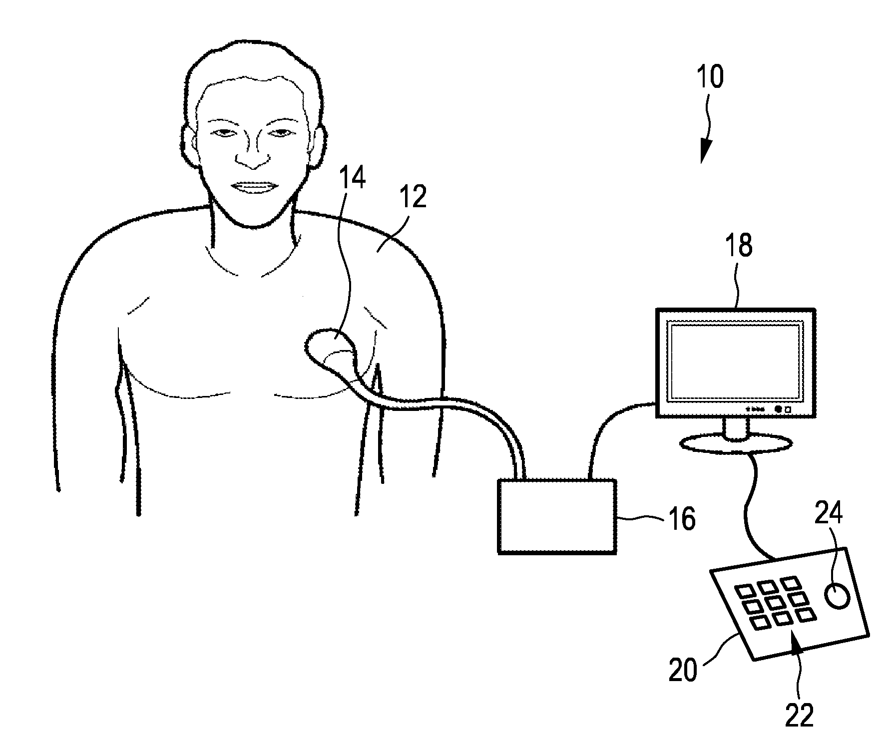
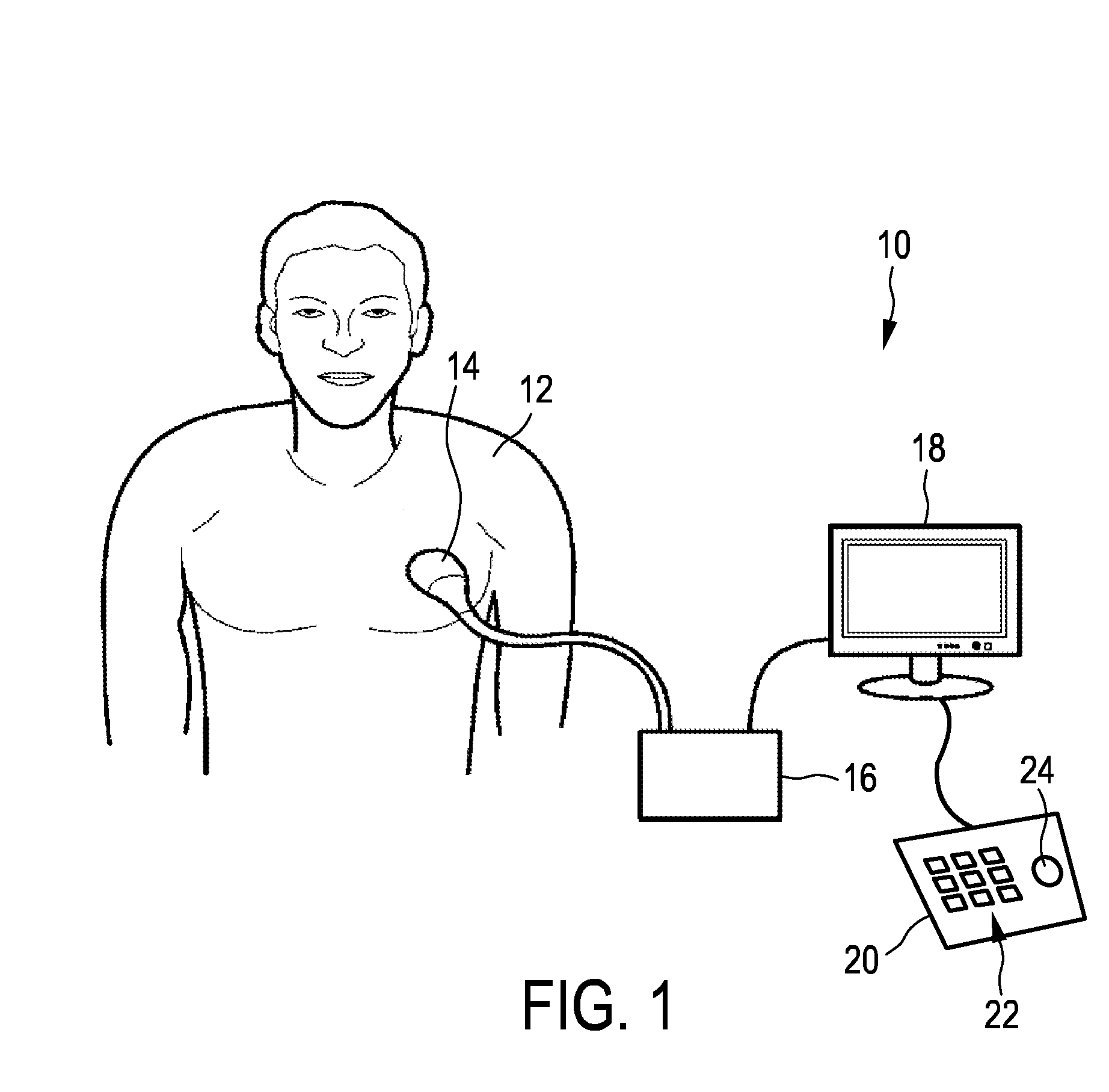
[0047]FIG. 4 shows a schematic block diagram of the ultrasound system10. As already laid out above, the ultrasound system 10 comprises an ultrasound probe (PR) 14, the controlling unit (CU) 16, the display (DI) 18 and the input device (ID) 20. As further laid out above, the probe 14 comprises a phased two-dimensional transducer array 26. In general, the controlling unit (CU) 16 may comprise a central processing unit that may include analog and / or digital electronic circuits, a processor, microprocesso...


PUM


Abstract

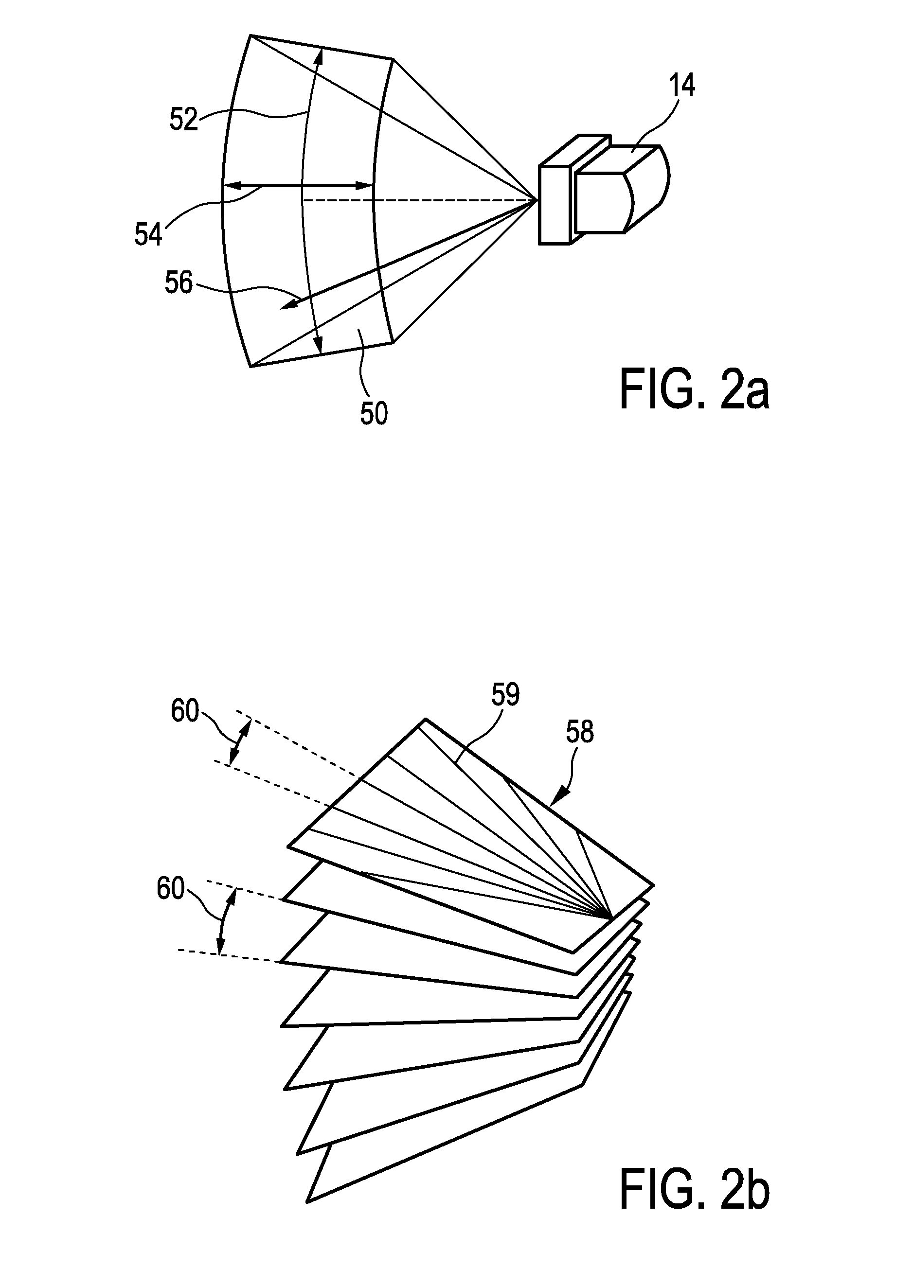
The present invention relates to a method for providing a three-dimensional ultrasound image of a volume (50) and an ultrasound imaging system (10). In particular, the current invention applies to live three-dimensional imaging. To improve three-dimensional dimensional ultrasound imaging of a large volume, it is contemplated to adjust the central receive frequency (70) of a bandpass filter (35) of a signal processor (34) as a function of a spacing (60) of scanning lines (59) of a transducer array (26).

Description

FIELD OF THE INVENTION[0001]The present invention relates to an ultrasound system and method for providing a live three-dimensional image of a volume, for example an anatomical site of a patient. The present invention further relates to a computer program for implementing such method.BACKGROUND OF THE INVENTION[0002]In three-dimensional ultrasound imaging, or volume imaging, the acquisition of a three-dimensional image is accomplished by conducting many two-dimensional scans that slice through the volume of interest. Hence, a multitude of two-dimensional images is acquired that lie next to another. By proper image processing, a three-dimensional image of the volume of interest can be built out of the multitude of two-dimensional images. The three-dimensional information acquired from the multitude of two-dimensional images is displayed in proper form on a display for the user of the ultrasound system.[0003]Further, so-called live three-dimensional imaging, or 4D imaging, is often us...

Claims


Application Information

Patent Timeline
IPC IPC(8): A61B8/08A61B8/14
CPCA61B8/483A61B8/14G01S7/52026G01S15/8993A61B8/466A61B8/467A61B8/5207A61B8/0883A61B8/4488A61B8/465A61B8/463G01S15/89
Inventor SNYDER, RICHARD ALLEN
Owner KONINKLJIJKE PHILIPS NV
Learn More