
Luminescent solar concentrator with nanostructured luminescent layer

a technology of luminescent layer and solar concentrator, which is applied in the direction of optics, instruments, optical elements, etc., can solve the problems that lscs have not yet fulfilled their promise, and achieve the effect of improving efficiency

Inactive Publication Date: 2014-10-23
SIGNIFY HLDG BV
View PDF4 Cites 4 Cited by
  • Summary
  • Abstract
  • Description
  • Claims
  • Application Information

AI Technical Summary

Benefits of technology

The invention is a device called a luminescent solar concentrator, which is designed to capture more light and minimize the re-absorption of emitted light. The technical effect of this is improved efficiency of the device.

Problems solved by technology

LSCs have not yet made true their promise because of their small efficiency due to unwanted losses.

Method used


Image

  • Luminescent solar concentrator with nanostructured luminescent layer
  • Luminescent solar concentrator with nanostructured luminescent layer
  • Luminescent solar concentrator with nanostructured luminescent layer

Examples


Embodiment Construction

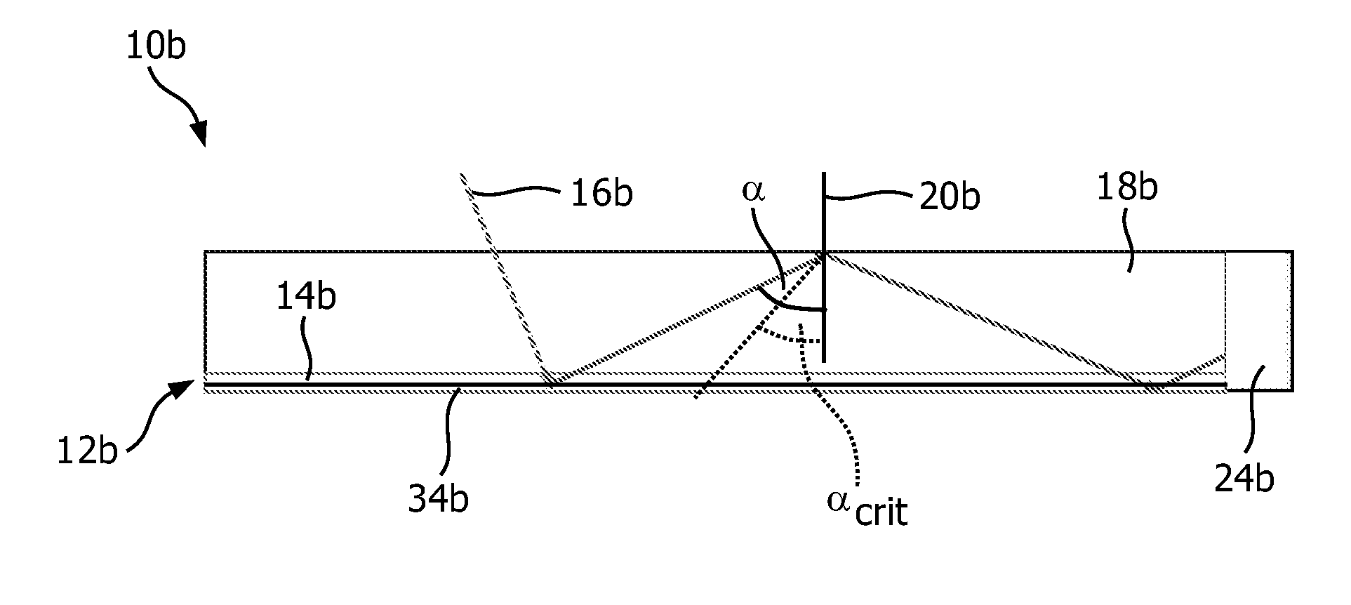
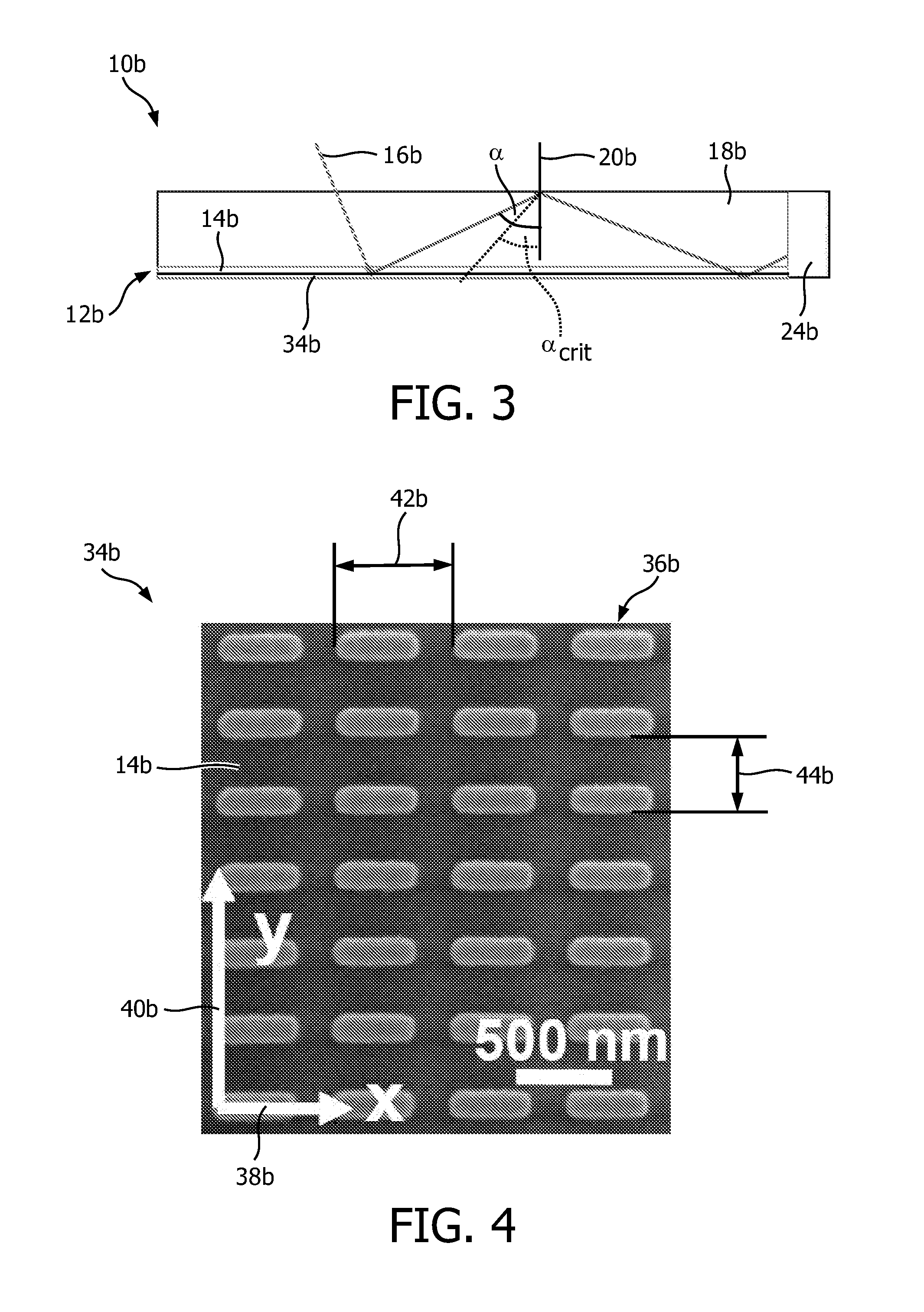
[0030]This description may comprise several embodiments of the invention. Like features, members and functions are generally labeled with like reference numerals. For distinguishing purposes, suffixes a, b, . . . are appended to the reference numerals for the various embodiments. For a missing description of the function of a like feature in one embodiment, reference is herewith made to the description of the function of that feature for the first embodiment.

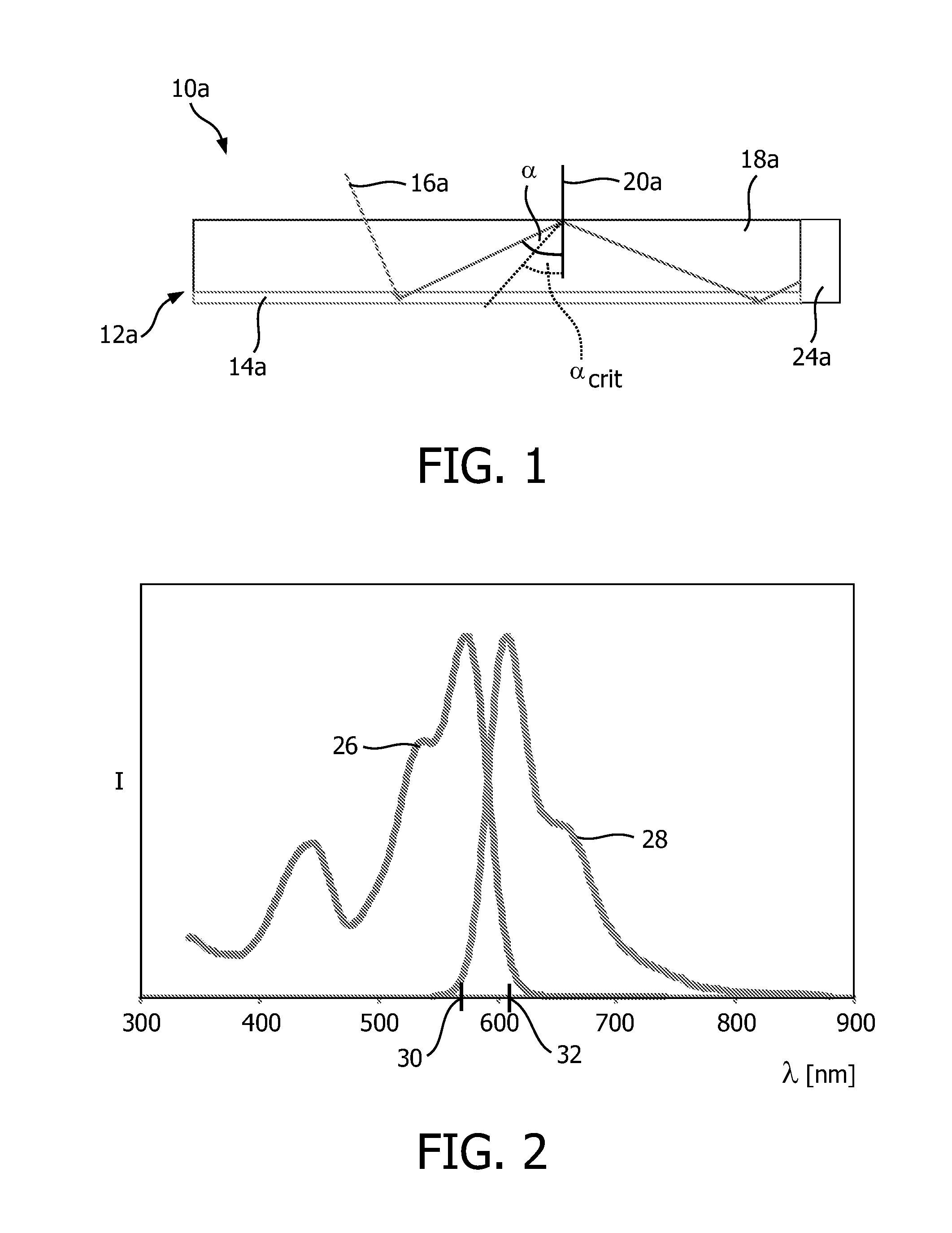
[0031]FIG. 1 schematically shows an embodiment of a photovoltaic generator 10a with a luminescent solar concentrator of the prior art.

[0032]The luminescent solar concentrator comprises a luminescent device 12a for converting incident light in an operating-ready mode. The luminescent device 12a comprises a luminescent member 14a. In the operation-ready mode, the luminescent member 14a absorbs incident light 16a (dashed line in FIG. 1) and emits light at longer wavelengths λ into a light guide 18a.

[0033]The light guide 18a is for...


PUM


Abstract

A luminescent solar concentrator, comprising: at least one luminescent device (12) for converting incident light (16) in at least one operating mode, wherein the luminescent device (12) has at least one nanostructured layer (34) and at least one luminescent member (14), and wherein the nanostructured layer (34) is in close proximity to the luminescent member (14); and at least one light guide (18) that is designed to guide light in a direction by total internal reflection.

Description

FIELD OF THE INVENTION[0001]The invention pertains to a luminescent solar concentrator and a photovoltaic generator with at least one luminescent solar concentrator.BACKGROUND OF THE INVENTION[0002]The principle of a luminescent solar concentrator (LSC) is well known in the field of photovoltaic generators. A glass or plastic sheet may contain or may be coated with some kind of luminescent material that absorbs incident light and emits light at longer wavelengths. A fraction of the emitted light of longer wavelengths is trapped inside the glass or plastic sheet by total internal reflection and guided to an edge where it is coupled into a small-area, efficient solar cell. A prior art luminescent solar concentrator is, for instance, described in document WO 2010 / 023657 A2. LSCs are promising because they are low-cost and can shift an operating point of the solar cell to higher light intensities.[0003]LSCs have not yet made true their promise because of their small efficiency due to un...

Claims


Application Information

Patent Timeline
Patent Type & Authority Applications(United States)
IPC IPC(8): H01L31/0232H01L31/052G02B19/00
CPCH01L31/02327H01L31/0527G02B19/0042H01L31/055H01L31/056Y02E10/52
Inventor DE BOER, DIRK KORNELIS GERHARDUSGOMEZ RIVAS, JAIMERODIRGUEZ, SAID RAHIMZADEH-KALALEDIEDENHOFEN, SILKE LUZIA
Owner SIGNIFY HLDG BV
Learn More