
Blast/impact mitigation shield

a shield and impact technology, applied in protective equipment, manufacturing tools, transportation and packaging, etc., can solve the problems of inability to include a v-hull in vehicles, limit the amount of explosive blast that can be deflected, and damage vehicles. , to achieve the effect of reducing the risk of explosion

Active Publication Date: 2014-10-23
FOSTER-MILLER
View PDF1 Cites 8 Cited by
  • Summary
  • Abstract
  • Description
  • Claims
  • Application Information

AI Technical Summary

Benefits of technology

This patent describes a lightweight blast shield designed for protection against explosses in vehicles. The shield is made up of a plunger plate and a damping material that transitions from solid to viscous fluid state near the blades of the plunger plate. The damping material can be a heat-sensitive material that absorbs the energy of the blast and helps deflect it away from the vehicle. The shield can be used as a vehicle design or an attachment kit for blast mitigation. The invention also includes methods of manufacturing the shield and offers various designs to protect against blast explosions.

Problems solved by technology

Mines and improvised explosive devices (IEDs) can damage vehicles and injure or kill vehicle occupants.
There is a limit, though, to how much of the explosive blast can be deflected.
And, some vehicles cannot be engineered to include a V-hull.
Still other vehicles cannot be equipped with heavy armor.

Method used


Image

  • Blast/impact mitigation shield
  • Blast/impact mitigation shield
  • Blast/impact mitigation shield

Examples


Embodiment Construction

[0028]Aside from the preferred embodiment or embodiments disclosed below, this invention is capable of other embodiments and of being practiced or being carried out various ways. Thus, it is to be understood that the invention is not limited in its application to the details of construction and the arrangements of components set forth in the following description or illustrated in the drawings. If only one embodiment is described herein, the claims hereof are not to be limited to that embodiment. Moreover, the claims hereof are not to be read restrictively unless there is clear and convincing evidence manifesting a certain exclusion, restriction, or disclaimer.

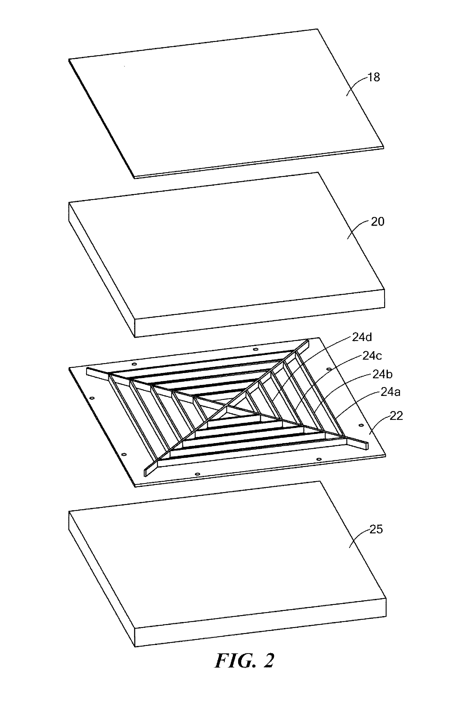
[0029]FIG. 1 shows military vehicle 12 equipped with shield 14 including, in this particular example, frame 16 bolted to the undercarriage “hull” of the vehicle. FIG. 2 shows one version (without the frame) where vehicle hull or a hull plate is depicted at 18. First body 20 abuts hull 18 and here is a slab of ultra high molecu...


PUM

PropertyMeasurementUnit
Nuclear radiationaaaaaaaaaa
Viscosityaaaaaaaaaa

Abstract

A method of manufacturing a shield by fabricating a plunger plate to include outwardly extending blades on one surface thereof and coupling the plunger plate to a body of damping material with blades of the plunger plate adjacent the body of damping material. The damping material is configured to transition from a solid to a non-flowing viscous fluid state locally near the blades of the plunger plate as they are driven into the body.

Description

RELATED APPLICATIONS[0001]This application is a continuation in part application of patent application Ser. No. 13 / 507,051.[0002]This application is also related to U.S. patent application Ser. No. 12 / 925,354 filed Oct. 19, 2010 which claims the benefit of and priority to U.S. Provisional Application Ser. No. 61 / 281,314 filed Nov. 16, 2009 under 35 U.S.C. §§119, 120, 363, 365, and 37 C.F.R. §1.55 and §1.78 each of which is incorporated herein by this reference. This application is also related to U.S. patent application Ser. No. 13 / 385,486 filed Feb. 22, 2012, and incorporated herein by this reference.FIELD OF THE INVENTION[0003]The subject invention relates to vehicle underbody blast effects and ballistic damage mitigation.BACKGROUND OF THE INVENTION[0004]Mines and improvised explosive devices (IEDs) can damage vehicles and injure or kill vehicle occupants. Some work has been carried out to detect and disable mines and IEDs. Other engineering concerns tailoring vehicles to be more ...

Claims


Application Information

Patent Timeline
IPC IPC(8): F41H5/04
CPCF41H5/04F41H5/0442F41H5/0457F41H7/042F42D5/045Y10T29/49826
Inventor PARIDA, BASANT K.DANA, NORMANZAOUK, ABDULLATIF K.XIN, XUDONG
Owner FOSTER-MILLER
Learn More