Image magnifying apparatus

Inactive Publication Date: 2014-10-09
JAWON MEDICAL
View PDF13 Cites 5 Cited by
  • Summary
  • Abstract
  • Description
  • Claims
  • Application Information

AI Technical Summary

Benefits of technology

This invention is an image magnifying apparatus that can be easily used by people with difficulty in controlling the orientation of the image capturing device, such as people with hand tremor or physical handicaps. The apparatus prevents image degradation from occurring by preventing a fingerprint of the user from contaminating the first lens. In this invention, the orientation of the image capturing device is automatically controlled depending on the target range and the second lens is automatically converted for focusing. The apparatus also prevents image distortion by aligning the second lens with the first lens. Additionally, the apparatus increases the intensity of light emitted from the lighting device when the target is located in a dark place to ensure a clear image is provided to the user.

Problems solved by technology

The low vision disability refers to a low visual recognition ability in which it is possible to recognize an object but impossible to recognize small font letters, and it is difficult to recognize an object or letter at a long distance because of a short focal distance.
However, such an operation method of the conventional image magnifying apparatus in which a user manually rotates the camera depending on the purpose of use inconveniences the user.
Particularly, in the case of a user such as the old, a hand tremor patient or a person with hand or arm dysfunction, it is very difficult to handle the apparatus.
Moreover, if a fingerprint is applied to a lens of the camera, an image degradation phenomenon is caused.
Degraded image quality may become a factor of gradually deterioration in the eyesight of a person with low vision.
In this case, the image is out of focus, and it is not easy for the user with low vision to determine whether the out-of-focusing problem is a problem resulting from incorrect setting of the diopter lens or not.
If the brightness of the place is comparatively low, an image degradation phenomenon may occur due to low illuminance.
This problem restricts a place where the image magnifying apparatus can be used, and the image quality inconveniences the user.

Method used


Image

  • Image magnifying apparatus
  • Image magnifying apparatus
  • Image magnifying apparatus

Examples


Embodiment Construction

[0037]Hereinafter, a preferred embodiment of the present invention will be described in detail with reference to the attached drawings so that those skilled in the art can easily embody the present invention. Furthermore, the present invention can be modified into various shapes rather than being limited to the following embodiment.

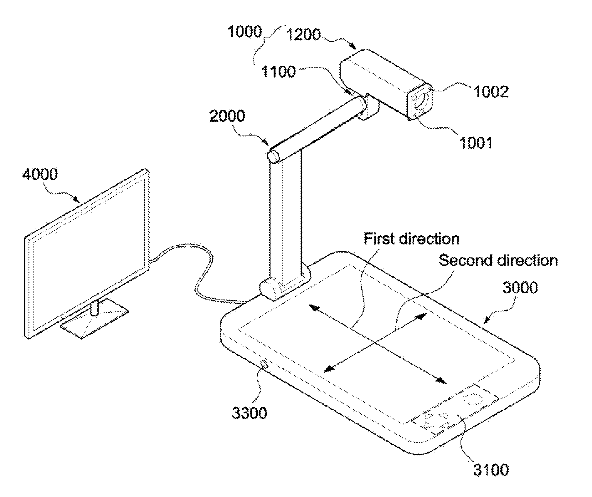
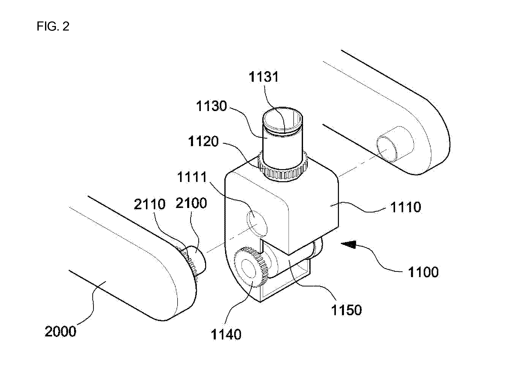
[0038]FIG. 1 is a perspective view illustrating an image magnifying apparatus according to the present invention. FIG. 2 is an exploded perspective view illustrating a critical part of a first drive unit according to the present invention. FIG. 3 is an exploded perspective view illustrating a critical part of a second drive unit according to the present invention. FIG. 4 is a sectional view showing an embodiment of the first drive unit according to the present invention. FIG. 5 is a partially broken perspective view illustrating a critical part of a third drive unit according to the present invention. FIG. 6 is another partially broken perspective view il...


PUM


Abstract

Disclosed herein is an image magnifying apparatus which automatically brings a target into focus using a diopter lens depending on whether the target is at a short distance or at a long distance. The orientation of a camera and short- or long-distance focusing of a camera lens can be automatically controlled to provide a clear image to a user, whereby even a user with low vision, a blind user, an aged user, a hand tremor user, etc. can easily use the apparatus. Furthermore, the present invention provides lighting suitable for user environment, thus providing a clear image to the user.

Description

BACKGROUND OF THE INVENTION[0001]1. Field of the Invention[0002]The present invention relates generally to image magnifying apparatuses which automatically brings a target into focus using a diopter lens depending on whether the target is at a short distance or at a long distance, and more particularly, to an image magnifying apparatus in which the orientation of a camera and short- or long-distance focusing of a camera lens can be automatically controlled to provide a clear image to a user, whereby even a user with low vision, a blind user, an aged user, a hand tremor user, etc. can easily use the apparatus.[0003]2. Description of the Related Art[0004]Generally, visual impairment refers to a visual function disability resulting from damage in the visual system. According to an extent to which eyesight and a range of vision are limited, visual impairment is classified into blindsight and low vision. The low vision disability refers to a low visual recognition ability in which it is ...

Claims


Application Information

Patent Timeline
IPC IPC(8): H04N5/225
CPCH04N5/2251H04N5/74H04N5/2253H04N23/50H04N23/54G03B21/06
Inventor YOON, YANG TAIKCHOI, KYEONG SEONLEE, SANG JUN
Owner JAWON MEDICAL
Why Eureka
Try Eureka