
Vertically stowed tray table assembly with translational movement

a tray table and vertical movement technology, applied in the direction of transportation and packaging, seating arrangements, aircraft crew accommodation, etc., can solve the problems of complex hinge assembly and armature, inconvenient storage, and increased complexity of storage compartments,

Active Publication Date: 2014-10-09
BE AEROSPACE INCORPORATED
View PDF19 Cites 31 Cited by
  • Summary
  • Abstract
  • Description
  • Claims
  • Application Information

AI Technical Summary

Benefits of technology

The patent describes a tray table assembly for a passenger seat in an aircraft. The assembly includes a horizontal rail along the seat, a carriage assembly that moves along the rail, and a tray table that pivots between a vertical and horizontal position. The tray table can be raised and lowered using a gas spring, and it can be rotated during deployment using a damper. The assembly can also include a second horizontal rail and a ledge that interferes with the carriage assembly to prevent it from lowering until it is clear of the ledge. The technical effects of the invention include improved access to a tray table for passengers and a more convenient and comfortable way to use the table while in flight.

Problems solved by technology

In seating arrangements in which there are no forward seats, tray tables commonly stow within a vertical pocket alongside the seat, and thus require complex hinge assemblies and armatures to lift, pivot and rotate the tabletop into place over the passenger's lap.
This is particularly inconvenient when the passenger intends on only briefly getting up, for example, to use the lavatory, or when the tabletop is supporting food and beverages that are difficult to store elsewhere.
Tray tables that store alongside the seat within a vertical pocket are also disadvantageous in that a storage compartment adds complexity and weight, and consumes valuable floor and seat space.

Method used


Image

  • Vertically stowed tray table assembly with translational movement
  • Vertically stowed tray table assembly with translational movement
  • Vertically stowed tray table assembly with translational movement

Examples


Embodiment Construction

[0034]The present invention will now be described more fully hereinafter with reference to the accompanying drawings in which exemplary embodiments of the invention are shown. However, the invention may be embodied in many different forms and should not be construed as limited to the representative embodiments set forth herein. The exemplary embodiments are provided so that this disclosure will be both thorough and complete, and will fully convey the scope of the invention and enable one of ordinary skill in the art to make, use and practice the invention. Like reference numbers refer to like elements throughout the various drawings.

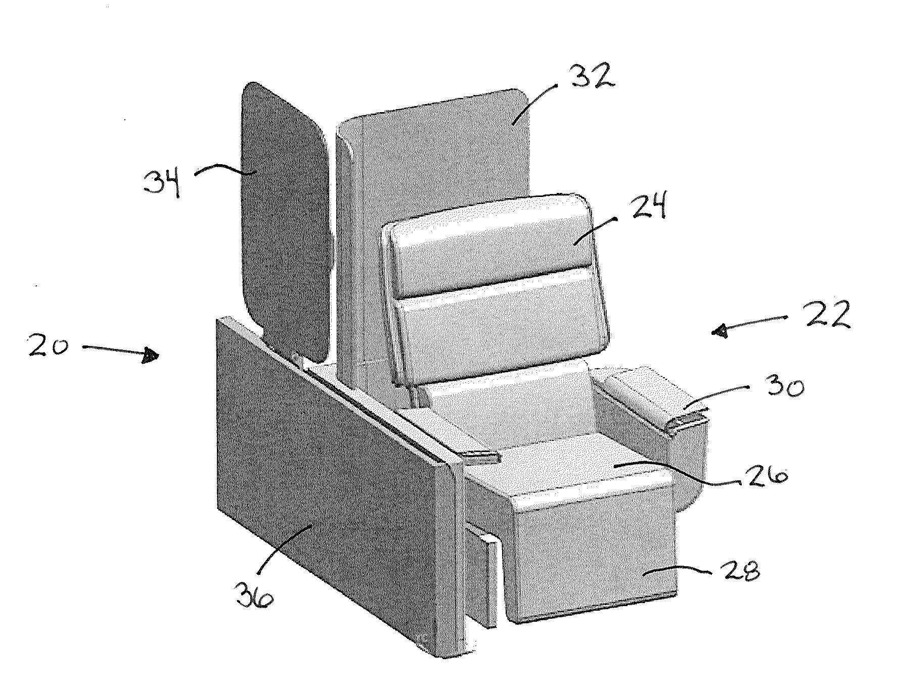
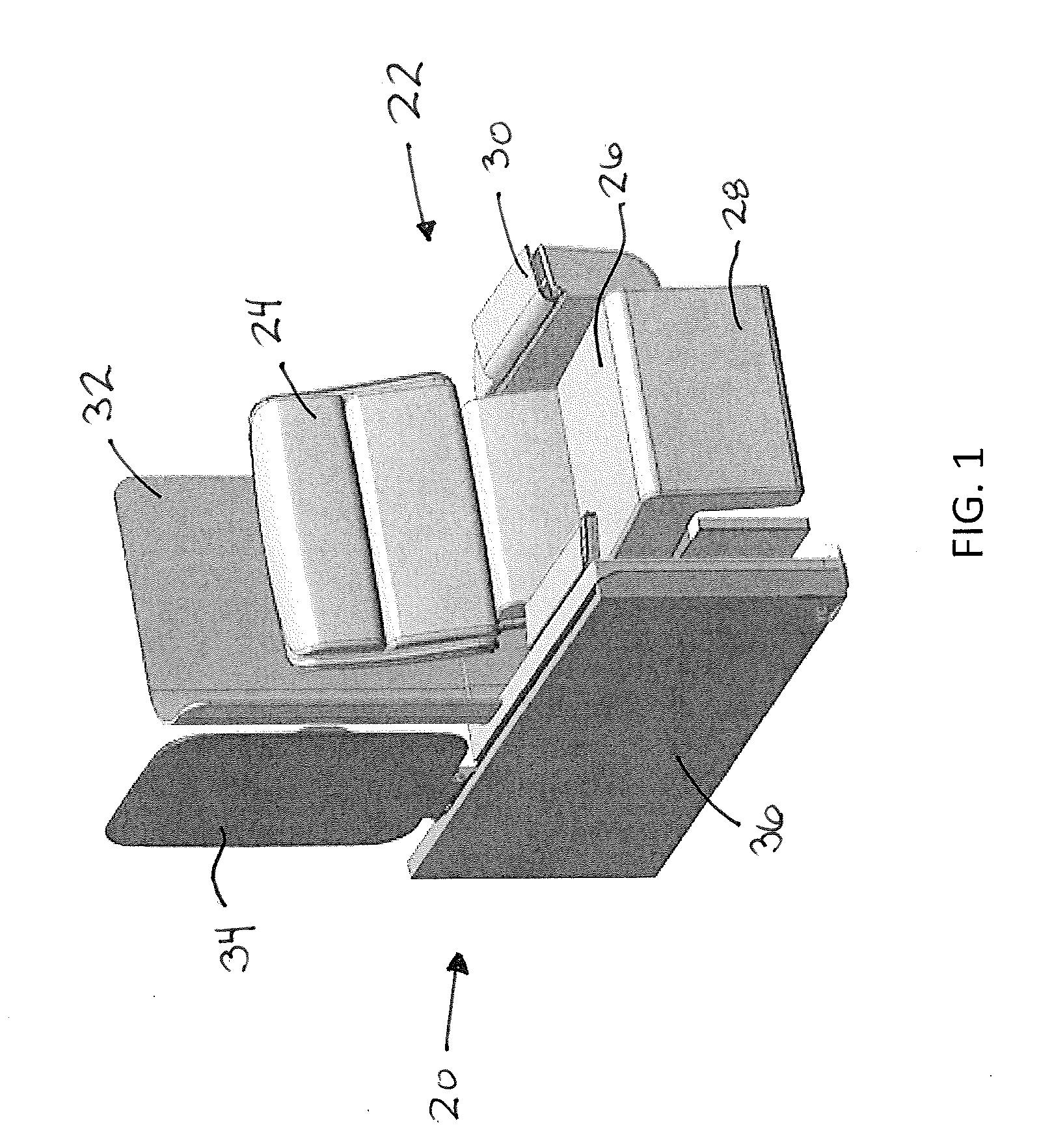
[0035]Referring to FIGS. 1-6, a tray table assembly according to an embodiment of the invention is shown generally at reference numeral 20. The tray table assembly 20 is shown arranged alongside an aircraft seat 22 for use by a seated passenger. The seat 22 can be any type of seat, for example, a coach class seat limited to a shallow recline or a premium...


PUM


Abstract

A tray table assembly for a passenger seat including a horizontal rail arranged alongside the seat, the horizontal rail having a length extending from the seatback to a position forward of the seat, a carriage assembly configured to travel horizontally along the rail, and a tray table attached to the carriage assembly, the tray table configured to pivot between a vertical orientation in which the tray table is stowed alongside the seatback and a horizontal orientation in which the tray table is positioned forward of the seatback.

Description

CROSS-REFERENCE TO RELATED APPLICATION[0001]This application claims priority from U.S. application Ser. No. 61 / 808,348 filed Apr. 4, 2013, the entirety of which is incorporated by reference herein.TECHNICAL FIELD AND BACKGROUND OF THE INVENTION[0002]The present invention relates generally to the field of tray table assemblies associated with passenger seats, and more particularly, to a tray table configured to slide along a rail adjacent a seat and move between a stowed vertical orientation alongside a seatback and a deployed horizontal position forward of the seatback.[0003]Tray tables are associated with most every type and class of aircraft seat to provide a passenger with a flat, horizontal tabletop for working, dining, etc. Tray tables are typically configured to move between a stowed position when not in use, such as during taxi, takeoff and landing, and a deployed position for use during flight. In coach class seating, tray tables are often attached to the back of a forward s...

Claims


Application Information

Patent Timeline
Patent Type & Authority Applications(United States)
IPC IPC(8): B64D11/06B60N3/00
CPCB60N3/002B64D11/06B60N2/242B64D11/0638
Inventor FROST, IAN LAWRENCEMOULTON, KRISTOPHER CHARLES
Owner BE AEROSPACE INCORPORATED
Learn More