Big gap element sealing system

a sealing system and element technology, applied in the direction of sealing/packing, borehole/well accessories, cable terminations, etc., can solve the problem that the element sealing system cannot create a seal with the surrounding casing

Active Publication Date: 2014-10-02
WEATHERFORD TECH HLDG LLC
View PDF9 Cites 23 Cited by
  • Summary
  • Abstract
  • Description
  • Claims
  • Application Information

AI Technical Summary

Problems solved by technology

However, when the cross-sectional thickness of the gap between the outer diameter of the liner and the inner diameter of the surrounding casing is larger than the pre-set cross-sectional thickness of the packing element, the conventional element sealing system is unable to create a seal with the surrounding casing.

Method used


Image

  • Big gap element sealing system
  • Big gap element sealing system
  • Big gap element sealing system

Examples


Embodiment Construction

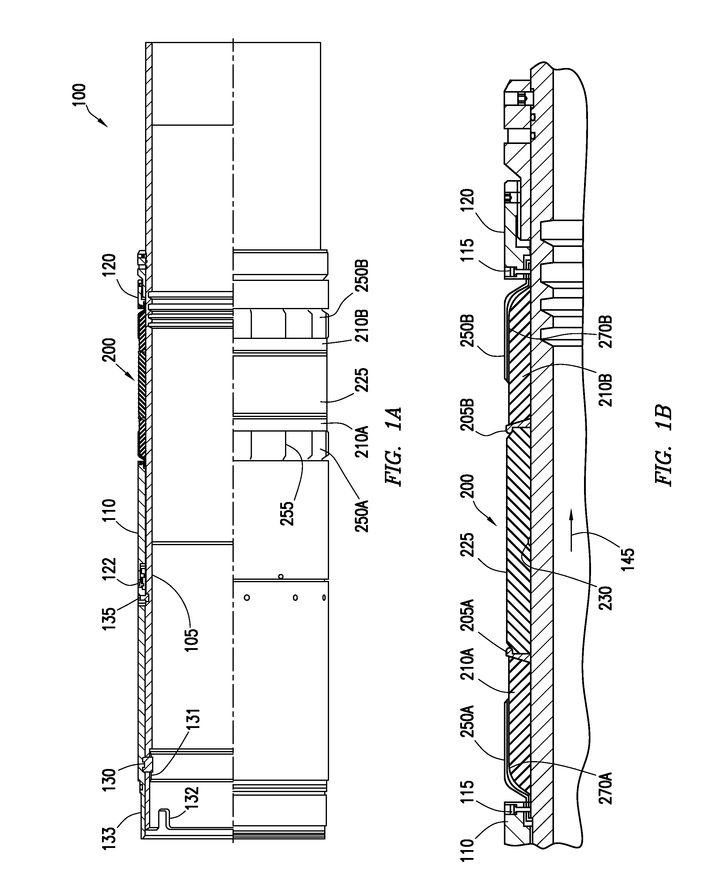
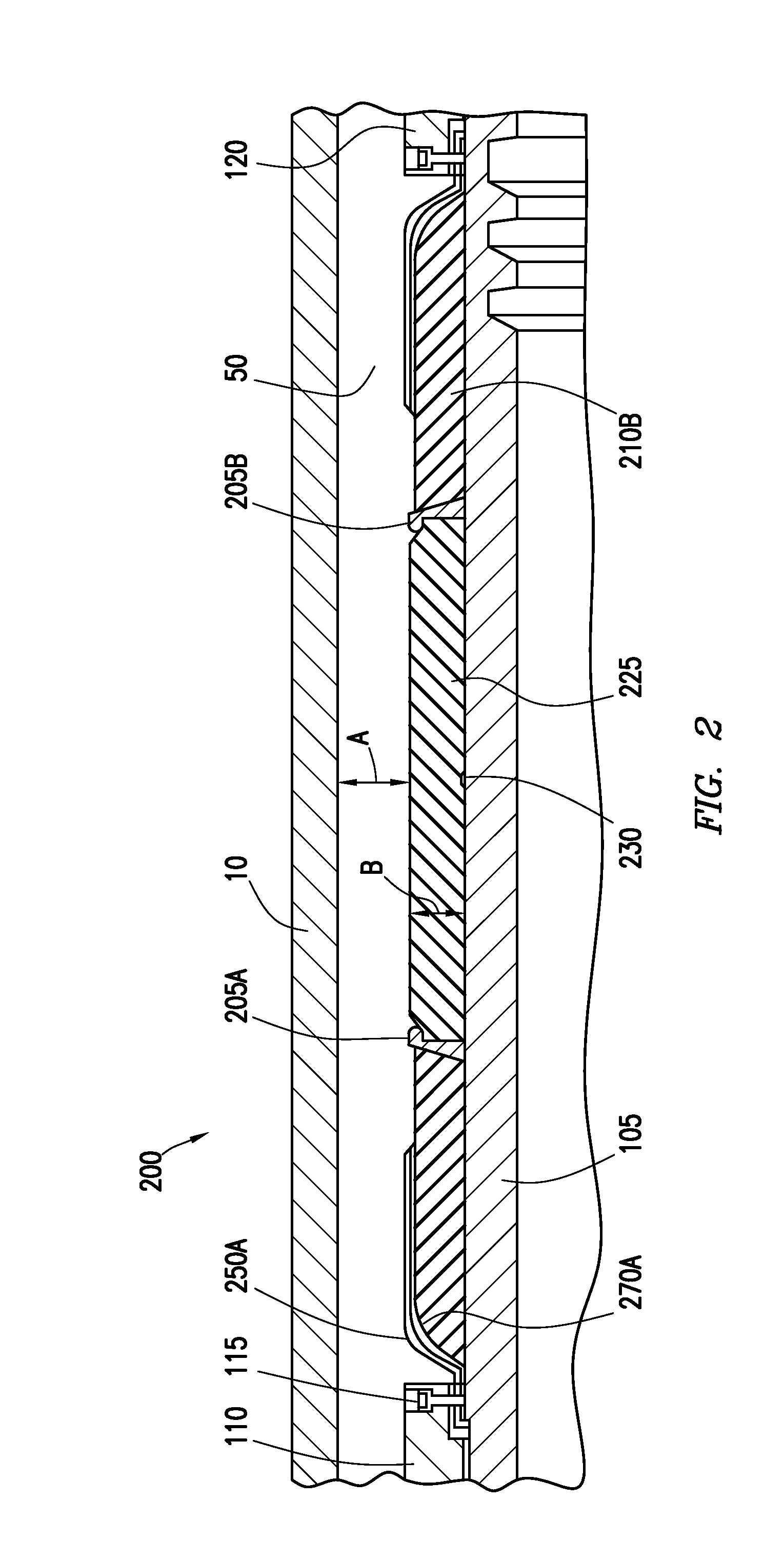
[0029]Embodiments of this disclosure generally relate to an element sealing system for a wellbore tool. The element sealing system will be described herein in relation to a liner-top packer. It is to be understood, however, that the element sealing system may also be used with other downhole tools without departing from principles of the present disclosure. Further, the element sealing system may be used in a wellbore tool that is disposed within a cased wellbore or within an open-hole wellbore. To better understand the element sealing system of the present disclosure and the methods of use thereof, reference is hereafter made to the accompanying drawings.

[0030]In one embodiment, a rubber packer seal assembly is provided to achieve a positive high temperature, high pressure seal in an annulus area where the annular sealing gap is greater than the available element thickness. This rubber packer seal assembly design includes multiple metal back-up rings, which deform under load (mecha...


PUM


Abstract

A sealing system includes a packing element having a groove in a surface thereof. The packing element is adapted to form a double hump configuration upon compression. The sealing system may include a first ring member disposed a first end of the packing element, a second ring member is disposed at a second end of the packing element, a first seal ring is disposed laterally outward of the first ring member, and a second seal ring is disposed laterally outward of the second ring member. A first inner back-up ring is disposed laterally outward of the first seal ring. The first inner back-up ring includes slots. A first outer back-up ring is disposed adjacent the first inner back-up ring and includes slots, wherein that slots in the first outer back-up ring are offset from the slots in the first inner back-up ring.

Description

BACKGROUND OF THE DISCLOSURE[0001]1. Field of the Disclosure[0002]Embodiments of this disclosure generally relate to a wellbore tool, and more particularly, to an element sealing system for a wellbore tool.[0003]2. Description of the Related Art[0004]A liner-top packer is run as an integral part of the liner hanger assembly to provide a reliable, high-integrity seal that isolates the gap between an outer diameter of the liner and an inner diameter of a surrounding casing. The liner-top packer is configured to provide pressure integrity, isolate the cement, and prevent gas migration or flow while the cement sets.[0005]The liner-top packer is normally set by setting down weight on the polished bore receptacle (PBR) with a packer actuator after the running tool is released. The weight is transferred to the liner-top packer to set a packing element in a conventional element sealing system.[0006]With the conventional element sealing system, the typical pre-set cross-sectional thickness o...

Claims


Application Information

Patent Timeline
Patent Type & Authority Applications(United States)
IPC IPC(8): E21B33/16E21B33/12
CPCE21B33/16E21B33/1208E21B33/1204E21B33/1216E21B43/10E21B33/165
Inventor NGUYEN, THOM T.TURLEY, ROCKY A.
Owner WEATHERFORD TECH HLDG LLC
Why Eureka
Try Eureka