
Interference suppression in blind spot monitoring

a technology of interference suppression and blind spot monitoring, applied in the field of detecting an approaching vehicle, can solve the problems of false warnings and errors, and the inability of sva ultrasonic sensors to differentiate, and achieve the effect of suppressing false warnings

Active Publication Date: 2014-09-25
ROBERT BOSCH GMBH
View PDF12 Cites 7 Cited by
  • Summary
  • Abstract
  • Description
  • Claims
  • Application Information

AI Technical Summary

Benefits of technology

The present invention relates to a device and method for driving assistance that can accurately identify the position of objects using ultrasonic sensors. The device can be installed in a motor vehicle and can detect the speed of approaching objects to prevent false warnings. This can improve safety during passing maneuvers and can be used with existing driving assistance systems. The technical effects of this invention are improved accuracy and safety for driving assistance systems.

Problems solved by technology

However, false warnings and errors may occur when one vehicle equipped with a side view assist system passes another vehicle also equipped with a side view assist system.
The reason for the false warning is that the SVA ultrasonic sensors are unable to differentiate whether they are detecting the reflection of their own transmitted pulse from the query signal or a signal from a different ultrasonic source.
This happens in particular since the query signals are not usually encoded by the corresponding vehicles and thus cannot be differentiated from one another.

Method used


Image

  • Interference suppression in blind spot monitoring
  • Interference suppression in blind spot monitoring
  • Interference suppression in blind spot monitoring

Examples


Embodiment Construction

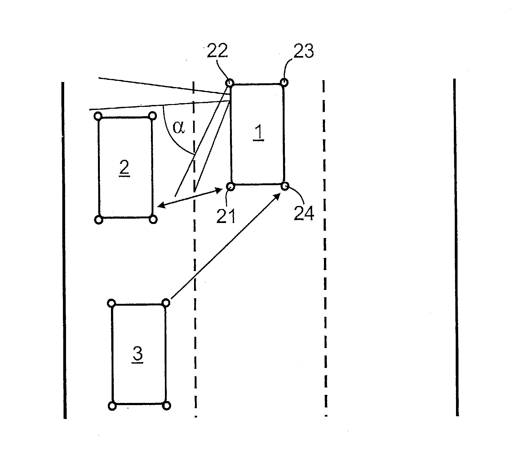
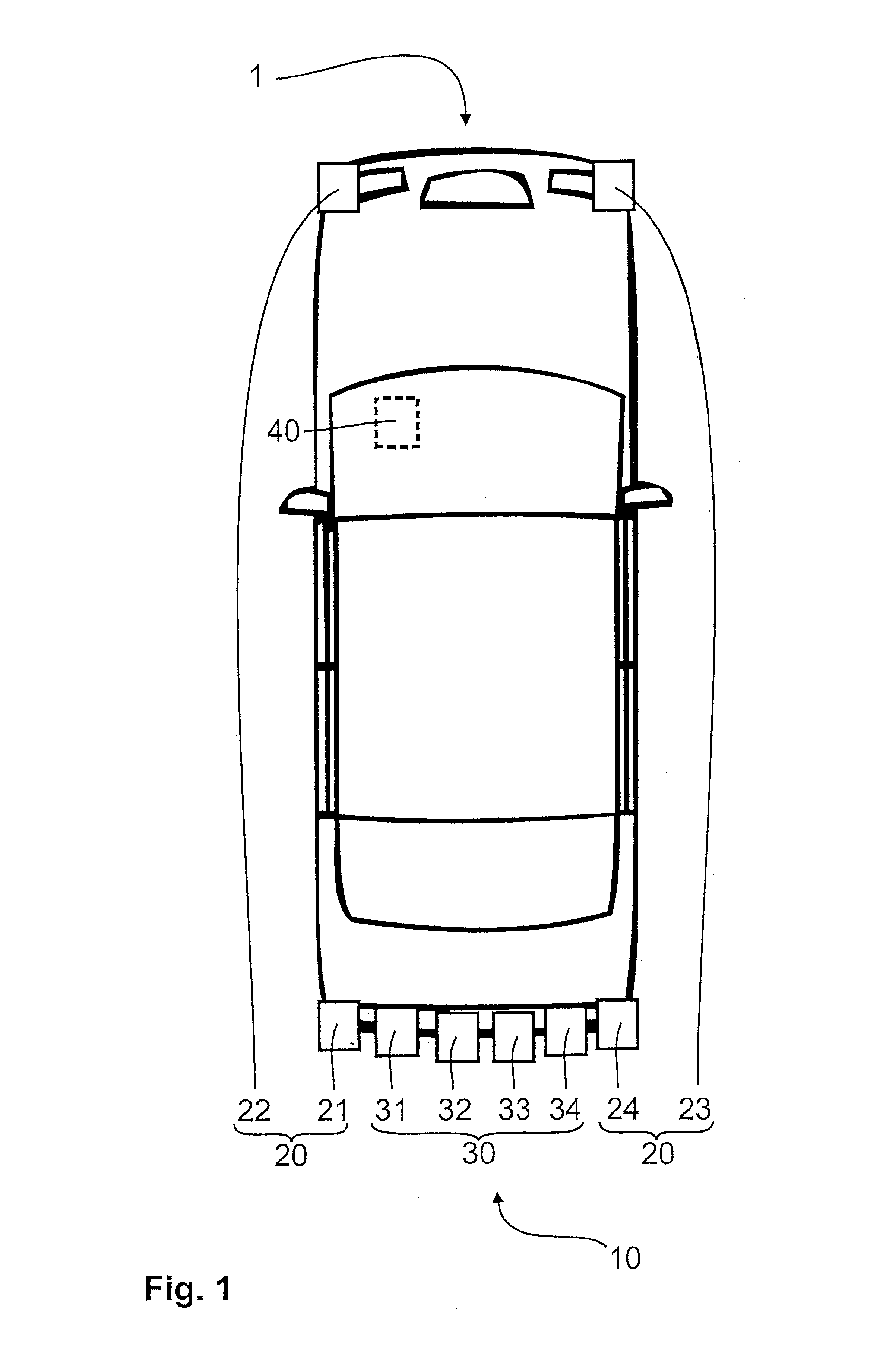
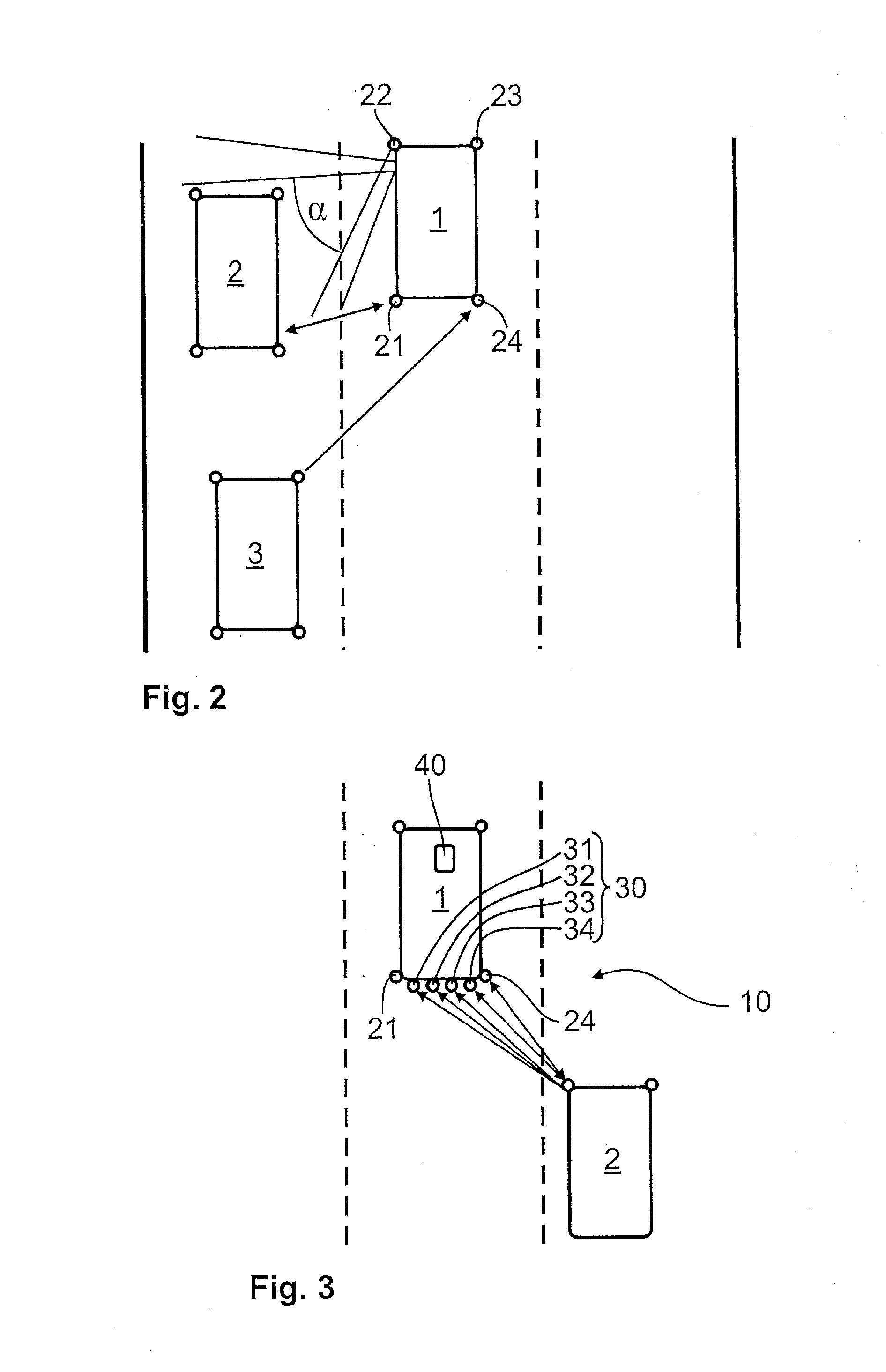
[0030]Elements having the same function and mode of operation are labeled with the same reference numerals in FIGS. 1, 2 and 3.

[0031]FIG. 1 illustrates a vehicle 1 according to the present invention, which has a side view assist system 20 having four SVA ultrasonic sensors 21, 22, 23, 24 as the first ultrasonic sensors and a driving assistance system 30 having four additional PP ultrasonic sensors 31, 32, 33, 34 as the second ultrasonic sensors. Four SVA ultrasonic sensors 21, 22, 23, 24 are situated on the side of vehicle 1. Two SVA ultrasonic sensors 21, 24 are provided in the rear of vehicle 1 and two SVA ultrasonic sensors 22, 23 are provided on the front of vehicle 1. Four PP ultrasonic sensors 31, 32, 33, 34 are situated in the rear end of the vehicle in the exemplary embodiment of the present invention shown here. PP ultrasonic sensors 31, 32, 33, 34 are mounted in a row between two rear SVA ultrasonic sensors 21, 24.

[0032]SVA ultrasonic sensors 21, 22, 23, 24 of side view as...


PUM


Abstract

A device for detecting a moving object in a blind spot includes: at least one first ultrasonic sensor of a side view assist system; and a control unit for determining the distance and / or speed and / or position of the moving object. The control unit processes at least one signal of a second ultrasonic sensor of a driving assistance system for monitoring the blind spot.

Description

BACKGROUND OF THE INVENTION[0001]1. Field of the Invention[0002]The present invention relates to a device and a method for detecting an approaching vehicle in a blind spot.[0003]2. Description of the Related Art[0004]There has been increasing use of assistance systems in modern automotive engineering; in particular, blind spot monitoring systems (side view assist, SVA) are known. These side view assist systems are capable of supporting the driver of a vehicle in a lane change or in backing out of a parking space.[0005]These systems are therefore capable of recognizing approaching vehicles and / or obstacles in a blind spot range. The driver of a vehicle equipped with such a side view assist system is then warned when an object is detected in the blind spot range. Side view assist systems have sensor systems for detecting other vehicles in a side lane and obstacles in the blind spot, these sensor systems generally being equipped with ultrasonic sensors.[0006]One such system is known, f...

Claims


Application Information

Patent Timeline
Patent Type & Authority Applications(United States)
IPC IPC(8): G01S15/93G01S15/931
CPCG01S15/931G01S15/876B60W30/18163B60W50/14B60W30/095B60W2420/54G01S15/878G01S2015/938G01S2013/9315
Inventor SCHOENHERR, SCHOENHERR
Owner ROBERT BOSCH GMBH
Learn More