
Magnetic field probe for MRI with a fluoroelastomer or a solution of a fluorine-containing compound

a technology of fluorine-containing compounds and magnetic field probes, which is applied in the direction of reradiation, measurement using nmr, instruments, etc., can solve the problems of affecting the signal-to-noise ratio, exceedingly short t2 relaxation time in solid form, and difficult to encapsulate substances, etc., to achieve stable oxidation and reduction

Active Publication Date: 2014-09-18
KONINKLJIJKE PHILIPS NV
View PDF8 Cites 4 Cited by
  • Summary
  • Abstract
  • Description
  • Claims
  • Application Information

AI Technical Summary

Benefits of technology

The patent text describes the use of Fluorine 19 (19F) as the active nucleus for magnetic field probes. This is advantageous because previous methods used perfluorinated hydrocarbons that are difficult to handle. The invention proposes alternative sources like perfluorinated polysiloxanes or fluorine-containing ionic liquids with optimized T1 / T2 ratios. The method also involves acquiring image magnetic resonance data and calculating corrected magnetic resonance data to accurately compensate for disturbances in the magnetic field and produce more accurate magnetic resonance images.

Problems solved by technology

These substances are either difficult to encapsulate and / or difficult to handle if in liquid form, or they have an exceedingly short T2 relaxation time in solid form.
The situation of a short T2 relaxation time in combination with a long T1 relaxation time adversely affects the signal-to-noise ratio of the 19F magnetic resonance measurement and, as a consequence, the field measurement becomes less accurate and / or more time consuming.

Method used


Image

  • Magnetic field probe for MRI with a fluoroelastomer or a solution of a fluorine-containing compound
  • Magnetic field probe for MRI with a fluoroelastomer or a solution of a fluorine-containing compound
  • Magnetic field probe for MRI with a fluoroelastomer or a solution of a fluorine-containing compound

Examples


Embodiment Construction

[0086]Like numbered elements in these figures are either equivalent elements or perform the same function. Elements which have been discussed previously will not necessarily be discussed in later figures if the function is equivalent.

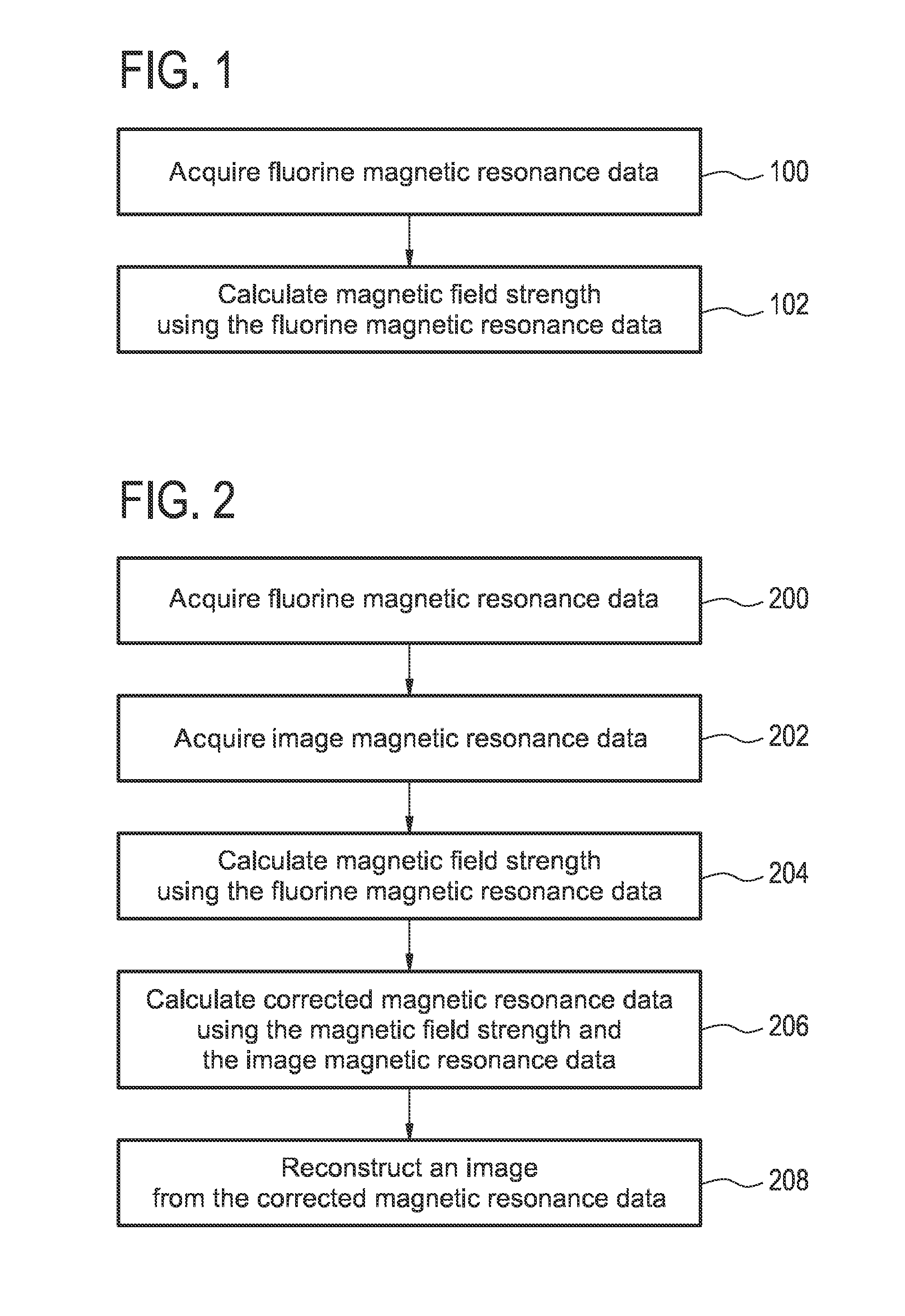
[0087]FIG. 1 shows a flow chart which illustrates a method according to an embodiment of the invention. In step 100 fluorine magnetic resonance data is acquired. Next in step 102 a magnetic field strength is calculated using the fluorine magnetic resonance data. In some embodiments the fluorine magnetic resonance data is acquired from multiple field probes. In this case the magnetic field strength at multiple spatial positions may be calculated. In addition the fluorine magnetic resonance data may be acquired at multiple time periods or continuously through the acquisition of image magnetic resonance data. As such the magnetic field strength may be spatially dependent and / or temporally dependent. That is to say a multi-dimensional magnetic field map whi...


PUM


Abstract

A method of measuring a magnetic field within a magnetic resonance imaging system (300) comprising a magnet (304) with an imaging zone (308) and a radio-frequency transceiver (316). The magnetic resonance imaging system further comprises a magnetic field probe (322) located within the imaging zone. The magnetic field probe comprises a fluorine sample (404) comprising any one of the following: a fluoroelastomer (700), a fluorine containing ionic liquid (600), and a solution of a fluorine containing compound. The field probe further comprises an antenna (406) for manipulating the magnetic spins of the fluorine sample and for receiving fluorine magnetic resonance data from the fluorine sample. The antenna is connected to the radio-frequency transceiver. The method comprises the steps of acquiring (100, 200) the fluorine magnetic resonance data using the magnetic resonance imaging system; and calculating (102, 206) a magnetic field strength (344) using the fluorine magnetic resonance data.

Description

TECHNICAL FIELD[0001]The invention relates to the quantitative measurement of magnetic field strengths in magnetic resonance imaging systems, in particular without limitation to the use of Fluorine for making the magnetic field measurements.BACKGROUND OF THE INVENTION[0002]During magnetic resonance imaging the magnetic field may vary during the acquisition of the magnetic resonance image. For instance the switching of the magnetic field gradients may introduce unwanted magnetic field variations. The placement of foreign objects or even the presence of tissue may affect the static magnetic field also. Magnetic measurements may be used for correcting for unwanted magnetic field variations.[0003]A magnetic field probe is a probe or sensor which enables the measurement of spatio-temporal variations in a magnetic field. A magnetic field probe may be constructed by taking a material which has a known Nuclear Magnetic Resonance (NMR) signal. The frequency of specific NMR resonances is a fu...

Claims


Application Information

Patent Timeline
Patent Type & Authority Applications(United States)
IPC IPC(8): G01R33/56
CPCG01R33/5601G01R33/24G01R33/34046G01R33/443G01R33/56563G01R33/58
Inventor FUDERER, MIHAPIKKEMAAT, JEROEN ALPHONS
Owner KONINKLJIJKE PHILIPS NV
Learn More