
Perineal retractor

a retractor and perineal technology, applied in the field of perineal retractors, can solve the problems of patient making this difficult to achieve, and achieve the effects of facilitating large-scale manual manipulation of the region, preserving a sterile environment, and minimizing direct effects

Inactive Publication Date: 2014-09-11
UNIVERSITY OF ROCHESTER
View PDF32 Cites 2 Cited by
  • Summary
  • Abstract
  • Description
  • Claims
  • Application Information

AI Technical Summary

Benefits of technology

The patent describes an apparatus and method for use during prostatectomy surgeries. The apparatus includes a curvilinear segment and a head portion with a surface for applying pressure to the perineum. The head portion can be placed against the perineum and a surgical drapery layer can be added for added protection. The apparatus helps to maintain a sterile environment and reduces direct, manual manipulation of the region. The technical effect of the invention is to facilitate the performance of prostatectomy surgeries, particularly robotically assisted surgeries, with improved efficiency and precision.

Problems solved by technology

The great utility of perineal pressure remains and while the patient is positioned well to allow for application of perineal pressure, the location of a robotic surgical machine directly between the legs of the patient makes this difficult to achieve.

Method used


Image

  • Perineal retractor
  • Perineal retractor
  • Perineal retractor

Examples


first embodiment

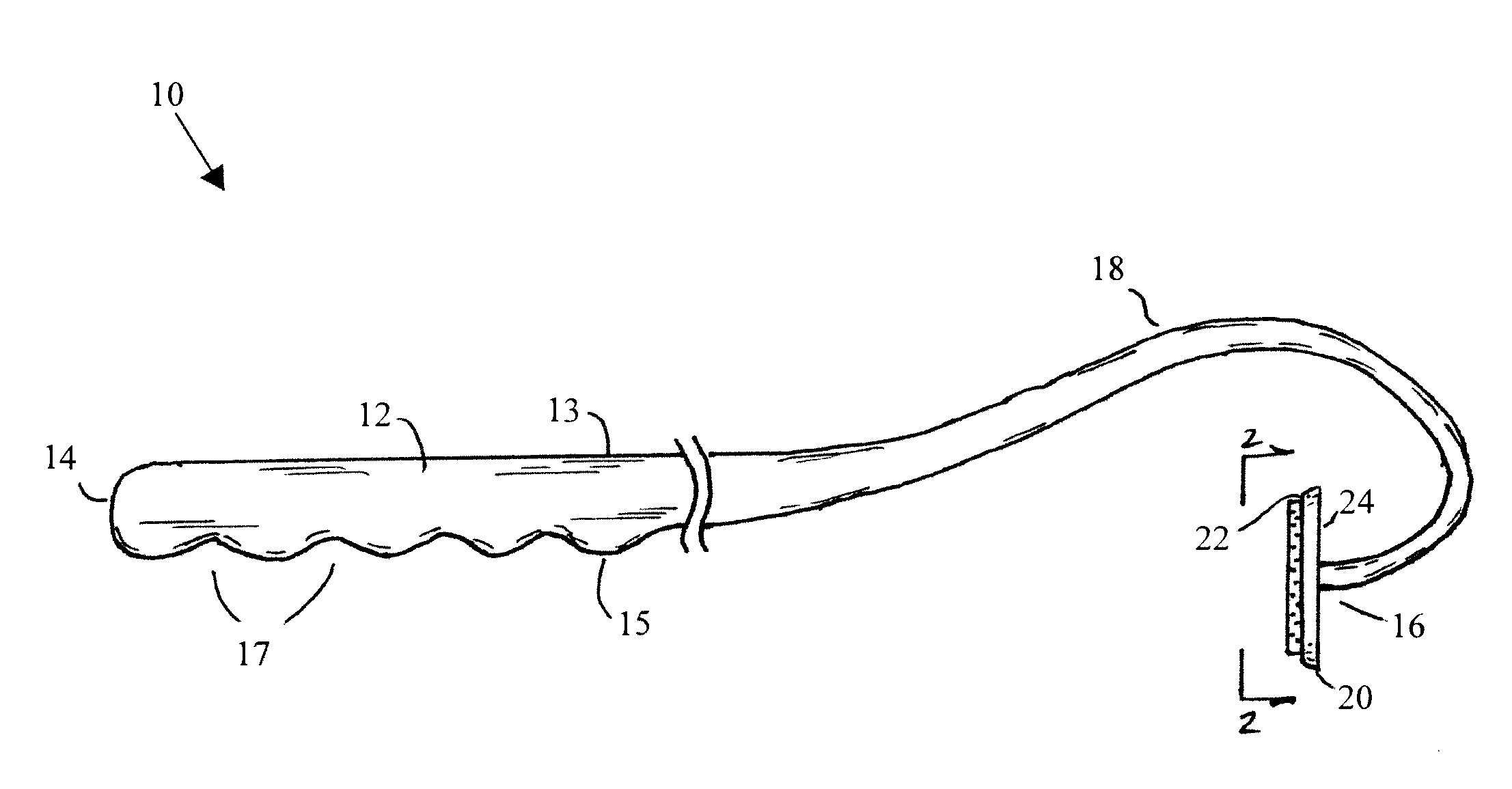
[0027]FIG. 1 illustrates the apparatus 10. This embodiment includes a handle portion 12 with a first end 14, a second end 16, and a curvilinear segment 18 between the first and second end. The curvilinear segment 18 has a gooseneck configuration such that the second end 16 faces in a direction toward the first end 14. The apparatus 10 also includes a head portion 20 including a first surface 22 on one side of the head portion 20 and a second surface 24 on an opposite side of the head portion 20. In this embodiment, the second surface 24 is integrally connected to the second end 16 of the apparatus 10. The handle portion 12 further includes an upper side 13 and a lower side 15 opposite the upper side 13, and a plurality of spaced indentations 17 disposed in the lower side 15 of the handle portion 12. This construction allows a user to grip and manipulate the apparatus 10 with a single hand while performing other tasks during the surgery with their free hand.

[0028]FIG. 2 illustrates t...

second embodiment

[0030]FIGS. 3 and 4 illustrate the apparatus 110. The handle portion 112 is largely identical to the handle portion 12 on apparatus 10, except at its second end 116. In this embodiment the head portion 120 includes a receiving member 132 adapted pivotally to connect the head portion 120 to the second end 116 wherein the second end 116 is pivotally moveable within the receiving member 132. This pivot connection enables the handle portion 112 to be freely movable by the user while the head portion 120 of the apparatus maintains its position to facilitate consistent delivery of pressure against the perineum of a patient. However, once an ideal location by the user is established, the pivotal connection between the head portion 120 and the second end 116 may optionally include a locking mechanism, such as a threaded screw set, to prevent pivotal movement of the second end 116 within the receiving member 132.

[0031]As shown, the second end 116 includes a ball formation 134 matingly receiv...


PUM


Abstract

An apparatus for perineal retraction during a prostatectomy includes a handle portion with a first end, a second end and a curvilinear segment between the first and second end. The second end faces in a direction toward the first end. The apparatus also includes a head portion including a first surface on one side of the head portion and a second surface on an opposite side of the head portion, the second surface being connected to or engageable with the second end of the handle. Use of the apparatus for perineal retraction during prostatectomy is also described.

Description

[0001]This application claims the priority benefit of U.S. Provisional Patent Application Ser. No. 61 / 774,697, filed Mar. 8, 2013, which is hereby incorporated by reference in its entirety.FIELD OF THE INVENTION[0002]This invention relates to a perineal retractor, optionally having portions thereof integrated into surgical drapery, and its use during a prostatectomy.BACKGROUND OF THE INVENTION[0003]Many surgeons use direct perineal pressure during open prostatectomy. Since the advent of robotically assisted prostatectomy in 2000, this type of minimally invasive surgery has become widespread, with now over 80% of the roughly 90,000 radical prostatectomies annually performed in the United States being conducted in this fashion. The great utility of perineal pressure remains and while the patient is positioned well to allow for application of perineal pressure, the location of a robotic surgical machine directly between the legs of the patient makes this difficult to achieve. Routinely...

Claims


Application Information

Patent Timeline
IPC IPC(8): A61B17/02A61B19/00
CPCA61B17/02A61B2017/0212A61B19/38A61B2017/00274A61B46/00A61B2046/205
Inventor LLOYD, GRANVILLE
Owner UNIVERSITY OF ROCHESTER
Learn More