
Rolling unit

a technology of rolling unit and rolling line, which is applied in the direction of metal rolling, metal rolling stand, manufacturing tools, etc., can solve the problems of increasing the structural complexity of the rolling unit, increasing the off-cuts of the head and tail end of the product that is rolled, and high cost and complexity of the adjustment device, so as to reduce the overall length of the rolling line

Active Publication Date: 2014-08-28
DANIELI & C OFF MEC SPA
View PDF6 Cites 0 Cited by
  • Summary
  • Abstract
  • Description
  • Claims
  • Application Information

AI Technical Summary

Benefits of technology

The patent describes a rolling stand with adjustable support elements that can be rotated eccentrically to adjust the gap between the rolls. This allows for better control of the rolling process and eliminates the need for roll guides between adjacent stands, making production simpler and more efficient. The adjustments can be made manually or with motorized equipment, and a reduction in the force required to achieve the adjustment can be achieved using reducer members. Overall, this patent offers a more flexible and efficient way to control the rolling process.

Problems solved by technology

This entails an increase in the structural complexity of the rolling unit, and also an increase in the off-cuts of the head and tail ends of the product that is rolled.
Furthermore, even in the case where it is possible to reduce the overall bulk of the rolling unit in order to put the rolling stands adjacent to each other, the adjustment device is very expensive and complex to obtain.
There is a consequent overall weakening of the bearing structure of the rolling unit and in particular of the bearing structure that supports the adjustment device.
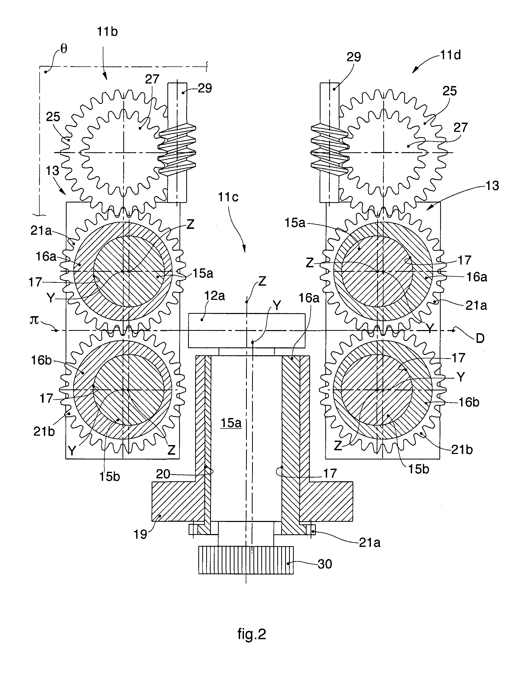
The position of the worm screw and the outermost toothed wheel determines an increase in the lateral bulk of the rolling stand, which does not allow to reduce the inter-stand space in the event of a close succession of stands in a rolling unit with two or more stands.

Method used


Image

  • Rolling unit
  • Rolling unit
  • Rolling unit

Examples


Embodiment Construction

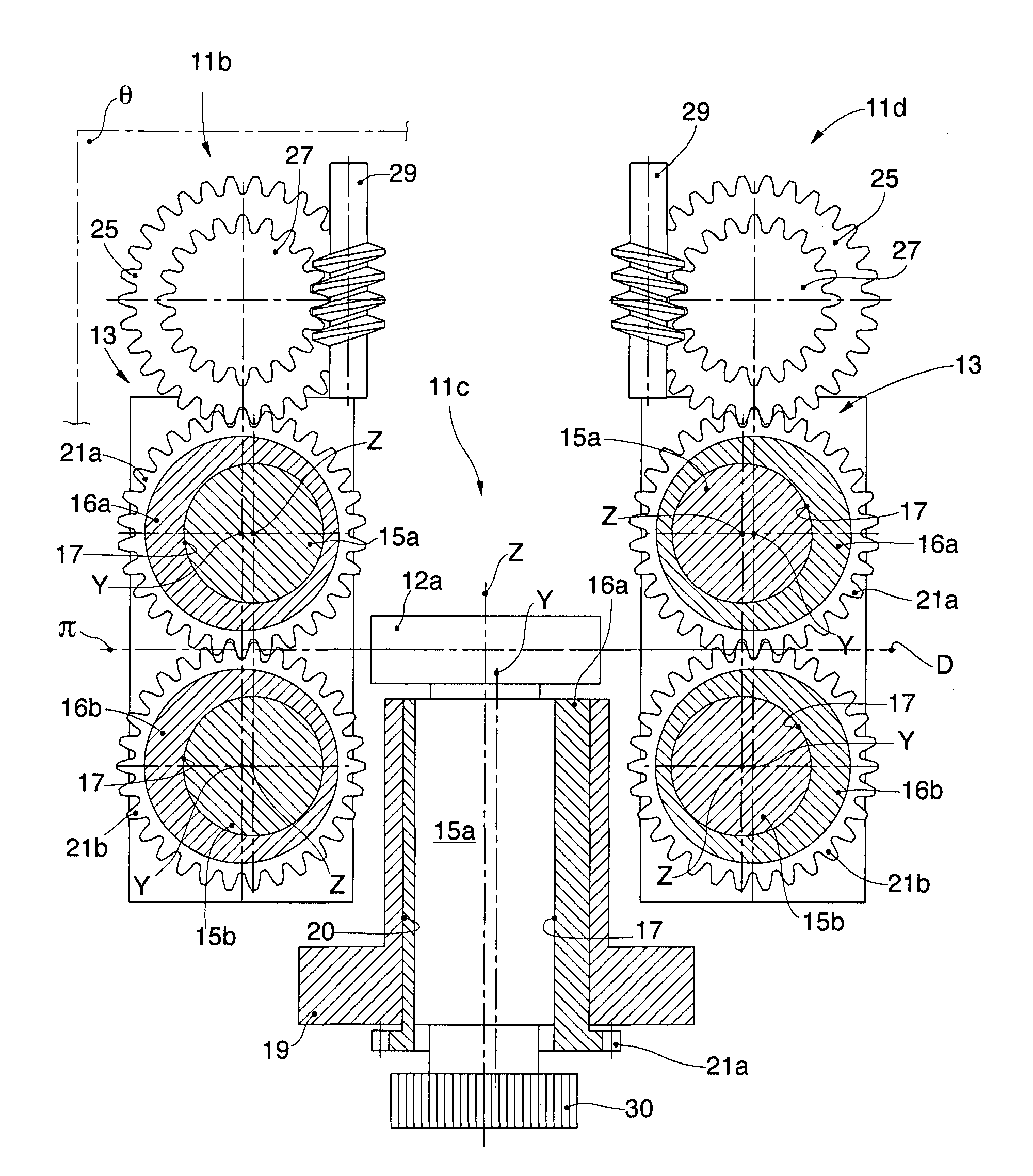
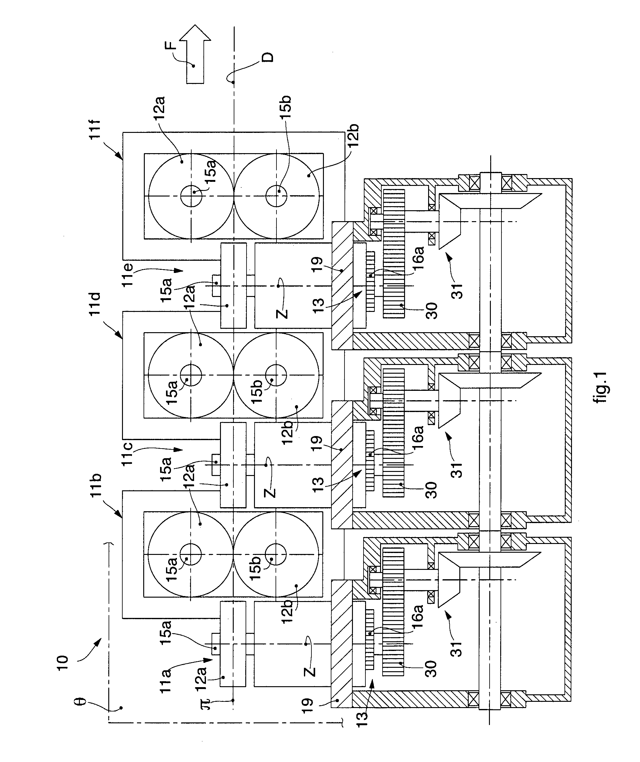
[0055]With reference to FIG. 1, a rolling unit is denoted in its entirety by the reference number 10 and comprises a plurality of rolling stands 11a, 11b, 11c, 11d, 11e, 11f, each provided with a first rolling roll 12a and a second rolling roll 12b. Each rolling stand 11a, 11b, 11c, 11d, 11e, 11f comprises an adjustment device 13 to adjust the gap between the rolls 12a, 12b which allows to adjust the degree of aperture between the rolls and hence to vary the section sizes of the product that is rolled.

[0056]The pair of rolls 12a, 12b of the rolling stand 11b lies on a first lying plane π which is angularly offset by 90° with respect to a second lying plane θ on which lie the pair of rolls 12a, 12b of the rolling stands 11a and 11c disposed respectively upstream and downstream of the rolling stand 11b. An analogous disposition of the rolls 12a, 12b also applies for the other rolling stands 11c, 11d, 11e and 11f.

[0057]Between the rolling rolls 12a, 12b a product to be rolled is made ...


PUM

PropertyMeasurementUnit
Timeaaaaaaaaaa

Abstract

Rolling unit including at least two adjacent rolling stands, each having a pair of rolling rolls mounted on respective motorized shafts. The rolls of one rolling stand are disposed orthogonal and close to those of the adjacent rolling stand. The shafts are eccentrically supported in respective support elements, which are selectively rotatable around their axis and are each provided with rotation means to cooperate mechanically with an adjustment member suitable to make the support elements selectively rotate to determine an adjustment of the gap between the rolls. The rotation means of one pair of the support elements are directly connected kinematically to each other. The adjustment member is disposed, with respect to the rolling stands, so that the center of its gear lies very close to the line joining the centers of the support elements, so that a substantial part is contained in the bulk defined by the rolling stand.

Description

FIELD OF THE INVENTION[0001]The present invention concerns a rolling unit comprising a plurality of rolling stands disposed adjacent to each other and in sequence, each provided with a pair of rolling rolls whose reciprocal aperture is determined by an adjustment device.[0002]In particular, the rolling unit according to the present invention allows to reduce the overall bulk and prevent the use of rolling guides between two adjacent rolling stands disposed in sequence.BACKGROUND OF THE INVENTION[0003]Rolling units are known, comprising rolling stands served by devices to adjust the gap between the rolls.[0004]The device to adjust the gap allows to adjust their aperture and hence the section size of the rolled product to be obtained. Moreover, the adjustment device allows, for example after grinding operations, to re-use the rolling rolls whose diameter can vary as a function of the mechanical operations to which they have been subjected.[0005]Each roll of a rolling stand is keyed to...

Claims


Application Information

Patent Timeline
IPC IPC(8): B21B31/26B21B13/00
CPCB21B31/26B21B13/001B21B1/18B21B13/005
Inventor VASU, MASSIMOMULINARIS, FABRIZIO
Owner DANIELI & C OFF MEC SPA
Learn More