Centrifugal separator
- Summary
- Abstract
- Description
- Claims
- Application Information
AI Technical Summary
Benefits of technology
Problems solved by technology
Method used
Image
Examples
first embodiment
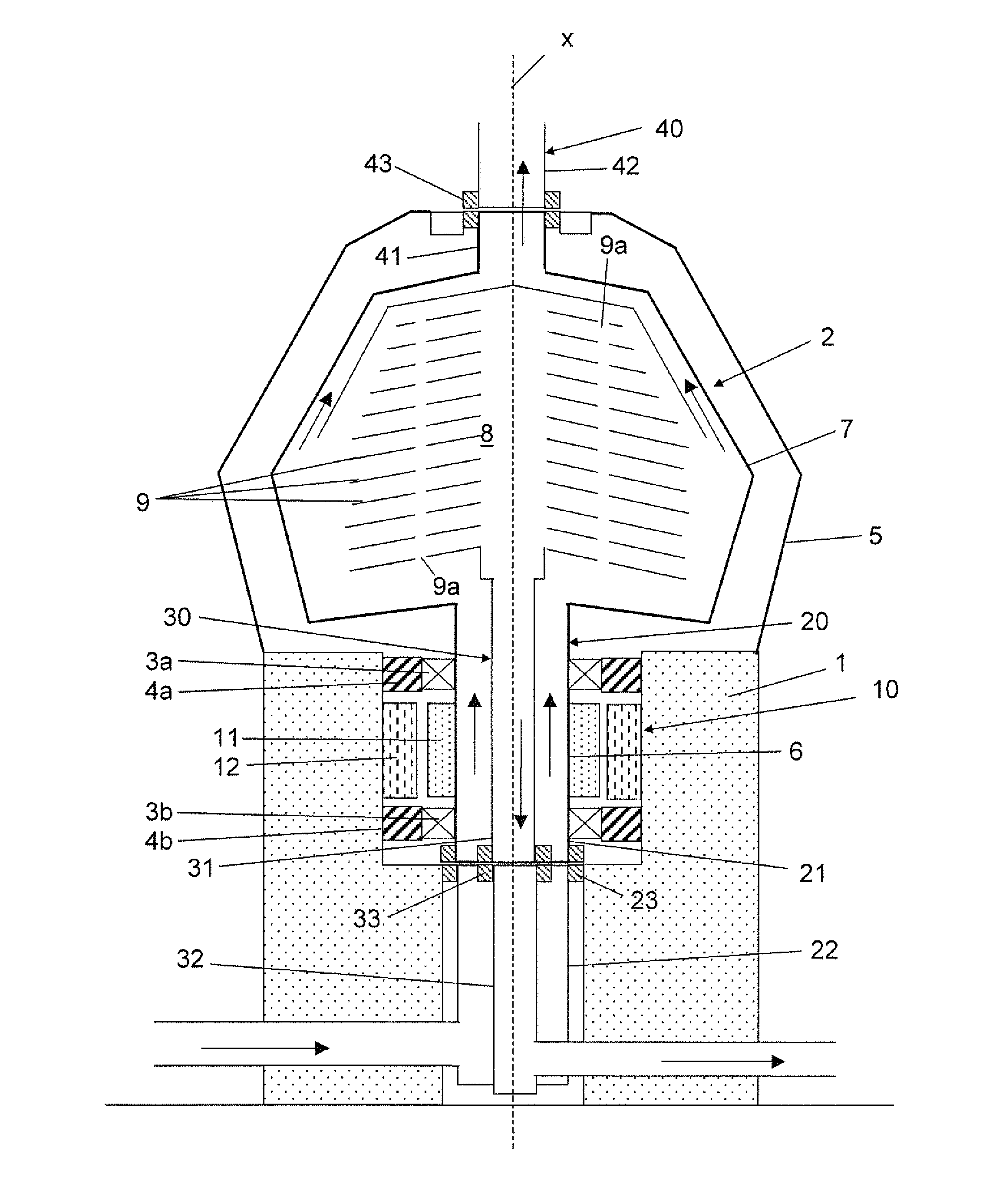
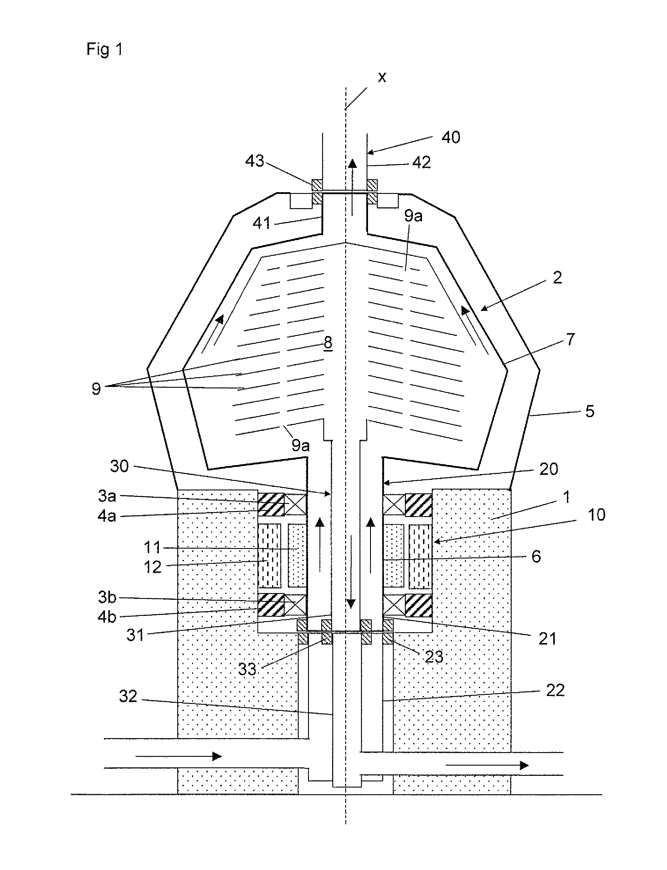
[0044]In the embodiment disclosed in FIG. 1, the primary phase of the product is a relatively light phase whereas the secondary phase of the product is a relatively heavy phase. Furthermore, the primary phase is the minor phase whereas the secondary phase is the main phase. These conditions may of course be the opposite in various variants of the first embodiment disclosed.
[0045]The inlet channel 20 and the outlet channel 30 are arranged adjacent to and concentrically with each other. In the first embodiment, the outlet channel 30 is provided within the inlet channel 20. It is of course possible, as an alternative solution, to provide the inlet channel 20 within the outlet channel 30.
[0046]The centrifugal separator also comprises forcing means provided to generate a leak flow through one of the sealing means, in the first embodiment the sealing means 33 of the outlet channel 30, in a first direction from the outlet channel 30 to the inlet channel 20, and thus to counteract or preven...
second embodiment
[0056]In the second embodiment, the pump wheel 70 is driven by a turbine wheel 71 via a drive shaft 72. The turbine wheel 71 is provided in the inlet channel 20 and driven by the fluid flow of the product fed through the inlet channel 20 into the separation space. However, as an alternative to the turbine wheel 71, the pump wheel 70 may be driven by an electrical motor via the drive shaft 72, or via a magnetic coupling, whereby the electrical motor may be provided inside or outside the rotating part 2.
[0057]In the second embodiment it may be dispensed with the pumping elements 60. The pumping effect of the pump wheel 70 may be sufficient to force a small part, i.e. the leak flow, of the primary phase through the sealing means 33. However, it is to be noted that the pump wheel 70 may be combined with pumping elements 60.
[0058]In the second embodiment, the rotary seal surface 36 and frame seal surface 38 of the outlet channel 30 are provided at a small distance from each other, i.e. w...
third embodiment
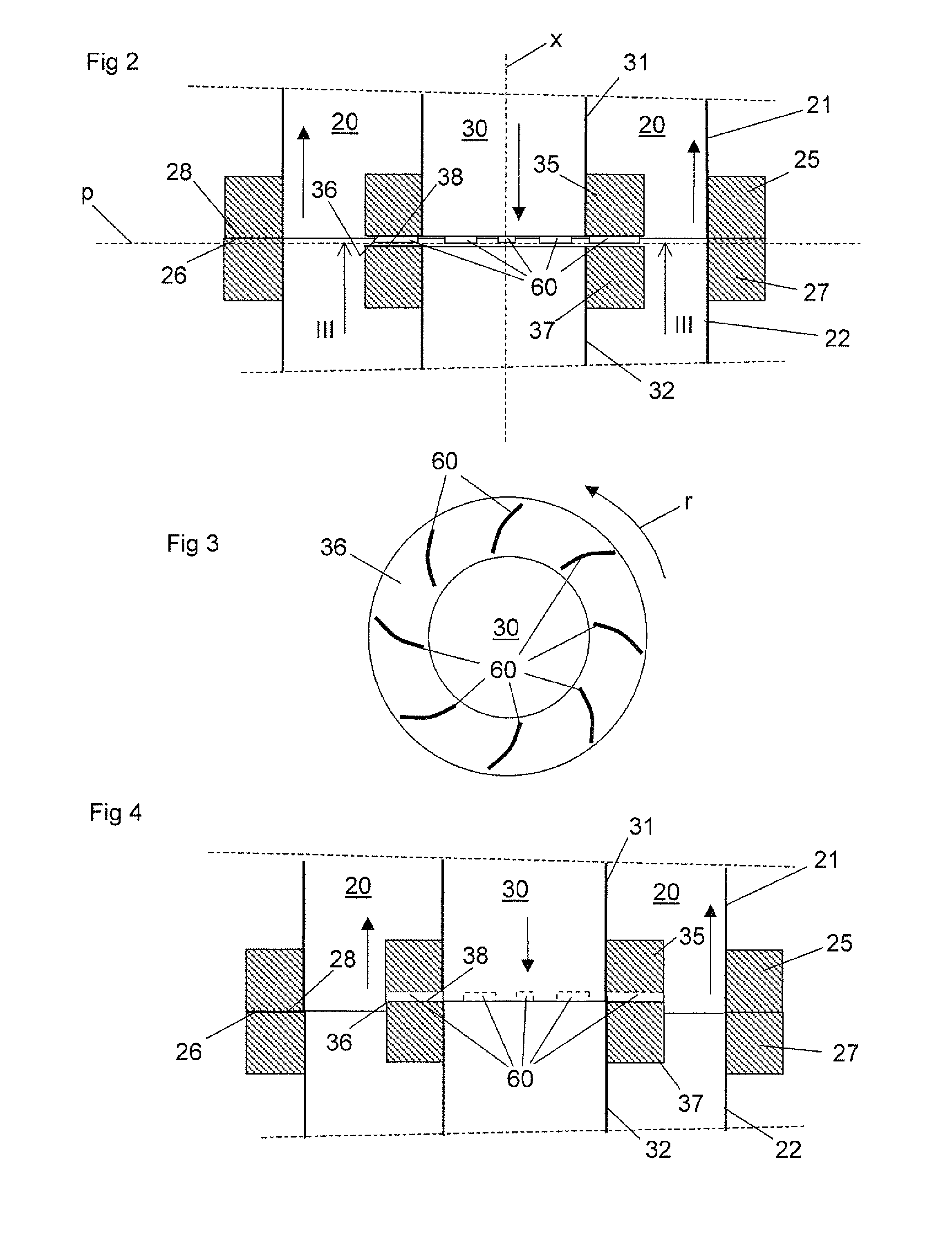
[0061]In the third embodiment, the forcing means comprises pumping elements 60 in the form of blades provided on the rotary seal surface 26 of the inlet channel 26 and the rotary seal surface 36 of the outlet channel 30. The blades on the rotary seal surface 26 and / or the rotary seal surface 36 may of course be replaced by grooves as disclosed in FIG. 4. The blades and / or grooves have the same configuration as the blades disclosed in FIGS. 2 to 4. Also in this case it is possibly to provide the pumping elements 60 on the frame seal surface 28 and / or the frame seal surface 38.
[0062]A fourth embodiment of the centrifugal separator differs from the one of the third embodiment in that the pumping elements 60 of the inlet channel 20 on the rotary seal surfaces 26 and / or the pumping elements 60 of the outlet channel 30 on the rotary seal surface 36 have been replaced by a pump wheel 70 of the second embodiment disclosed in FIG. 5. The seal surfaces 26, 28 and / or 36, 38 are arranged at a d...
PUM
 Abstract
Description
Claims
Application Information
 - R&D Engineer
- R&D Manager
- IP Professional
- Industry Leading Data Capabilities
- Powerful AI technology
- Patent DNA Extraction
Browse by: Latest US Patents, China's latest patents, Technical Efficacy Thesaurus, Application Domain, Technology Topic, Popular Technical Reports.
© 2024 PatSnap. All rights reserved.Legal|Privacy policy|Modern Slavery Act Transparency Statement|Sitemap|About US| Contact US: help@patsnap.com


