
Transmission line resonator, band-pass filter and branching filter

a technology of transceiver and bandpass filter, applied in the direction of resonators, electrical equipment, waveguides, etc., can solve the problems of high line impedance, limit in downsizing, and the resonator's size increases, so as to reduce the loss and higher q values, and reduce the size of the resonator

Active Publication Date: 2014-08-21
UNIVERSITY OF ELECTRO-COMMUNICATIONS
View PDF5 Cites 10 Cited by
  • Summary
  • Abstract
  • Description
  • Claims
  • Application Information

AI Technical Summary

Benefits of technology

The present invention relates to a transmission line resonator with distributed coupled lines. The technical effect of this invention is that it reduces loss and improves the quality of signal transmission by lowering the line impedance of the short-circuit grounding portion. Additionally, it reduces the size of the resonator by reducing the resonance frequency through an increase in the coupling coefficient of the distributed coupled lines. The use of this transmission line resonator with distributed coupled lines allows for the creation of small-sized, low-loss high-frequency circuits such as multi-staged band-pass filters, polarized filters, electronic tuning type filters, and multiplexers.

Problems solved by technology

The technical problem addressed in this patent text relates to finding ways to reduce the size of resonators while maintaining their performance in terms of reducing loss and improving quality value. Specifically, the text discusses the use of steved impedance resonators (SIRs) and how they may offer advantages such as smaller size but limitations exist in terms of achievable downsizing and reduced loss/higher Q values. Additionally, suggestions on alternative approaches like changing from uniform lines to SIRs or adding capacitance to improve downsizing are discussed.

Method used


Image

  • Transmission line resonator, band-pass filter and branching filter
  • Transmission line resonator, band-pass filter and branching filter
  • Transmission line resonator, band-pass filter and branching filter

Examples


Embodiment Construction

[0035]In embodiments of the invention, numerous specific details are set forth in order to provide a more thorough understanding of the invention. However, it will be apparent to one with ordinary skill in the art that the invention may be practiced without these specific details. In other instances, well-known features have not been described in detail to avoid obscuring the invention.

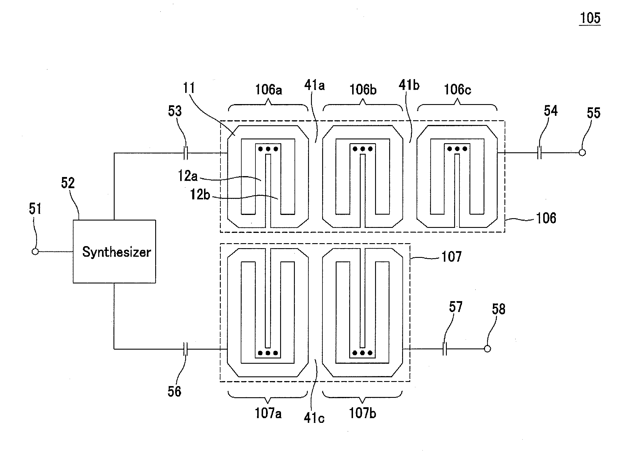
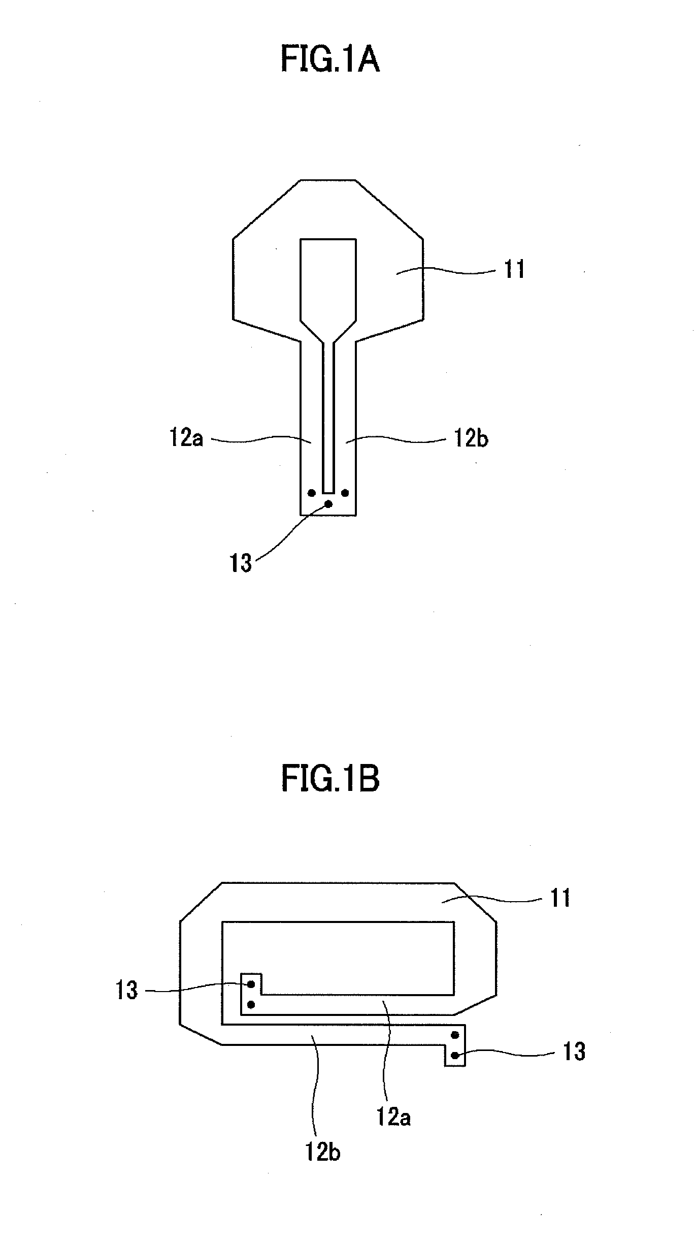
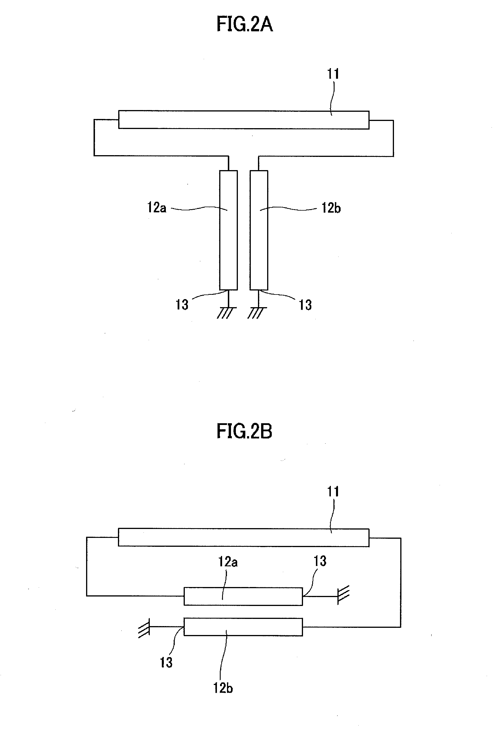
[0036]The transmission line resonator with distributed coupled lines to which one or more embodiments of the present invention is applied (hereinafter simply referred to as “transmission line resonator” or “resonator”), the band-pass filter, the cross-coupled filter, the electronic tuning type filter and the multiplexer using the transmission line resonator will now be explained in the following order with reference to the drawings.

[0037]1. Transmission line resonator

[0038]1-1. Configuration of the transmission line resonator

[0039]1-2. Operating principles of the transmission line resonator

[0040]1-3. ...


PUM


Abstract

A transmission line resonator includes distributed coupled lines including first distributed constant line which one ends are connected to a short-circuit grounding portion and second distributed constant line which is disposed in parallel to the first distributed constant line while being separated therefrom by a predetermined distance and which one ends opposing the short-circuit grounded one ends of the first distributed constant line are connected to the short-circuit grounding portion, and a single transmission line which both ends are connected to the respective other ends of the distributed coupled lines.

Description


Claims


Application Information

Patent Timeline
Owner UNIVERSITY OF ELECTRO-COMMUNICATIONS
Learn More